Blink a Light
The cyber:bot board has a built-in Propeller microcontroller on its underside. The Propeller has 32 digital input/output pins, called I/O pins for short, that are designed to interact with circuits. These are referred to by number, P0 through P31.
Some of the I/O pins are connected to circuits built into the cyber:bot board, that your robot is already using. For example, P16 through P19 are connected to 3-pin headers, where the servo motors are plugged into P18 and P19. In this activity, we will use P20 and P21, which are connected to tiny built-in LED lights. Later on, we will build circuits on the breadboard, and connect them to the sockets alongside labeled P0–P15. Projects sent to the micro:bit module can instruct the Propeller to interact with these built-in circuits.
Hardware Setup
- Set the cyber:bot board’s power (PWR) switch to Position 0.
- Make sure the battery holder is loaded with 5 AA batteries.
- Make sure the battery holder’s barrel plug is firmly plugged into the cyber:bot board’s barrel jack.
- Connect your micro:bit module to your computer with a USB cable.
Software Setup
- In a browser, go to makecode.microbit.org to open the micro:bit Makecode Editor.
- Make sure the cyberbot extension is added to the Project Files.
(See Add extensions to your micro:bit).
Blinking Lights
We’ll experiment with the “O” (output) feature of an I/O pin with a program to turn the built-in LED circuit on and off.
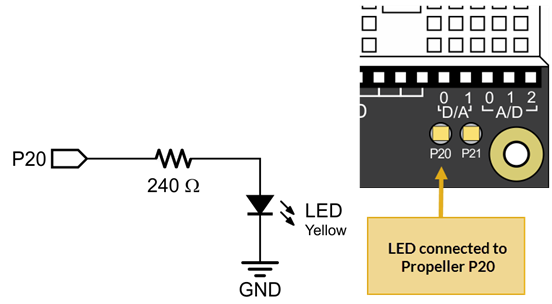
- Locate the small LED light.
On the cyber:bot, it’s a small part just above the P20 label in the lower-right corner of your board.
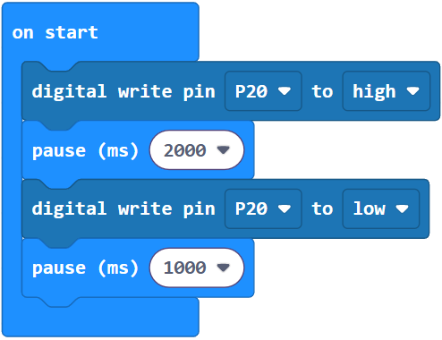
Example project: pin_20_blink
- Set the name to pin_20_blink and enter the project below.
(See Save & Edit Projects and Flash Projects with MakeCode Editor.) - Click Download.
(See Flash Projects with MakeCode Editor.) - Set the cyber:bot board’s PWR switch to 1.
- Watch the LED above the P20 label. It should blink slowly, once every 3 seconds.
How it works
By using the cyber:bot extensions write digital block instead of the already included digital write block, the command is then sent to the Propeller microcontroller instead of being processed by the micro:bit. From there, the Propeller uses its pre-programmed firmware to interact with circuits connected to its I/O pins.
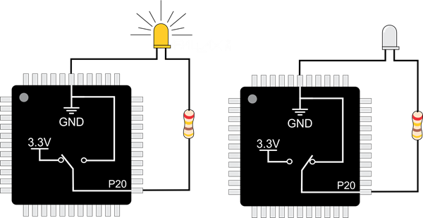
The block (Pin20) write digital (High) sets Propeller I/O pin P20 to “output high” which means it connects to its 3.3 V supply, as shown on the left side of the image below. The pin applies 3.3 V of electrical pressure to the LED circuit, causing electric current to pass through it and the light to turn on. After that, pause (2000) makes the program do nothing for 2000 ms, which keeps the light on for 2 seconds.
Next, (Pin20) write digital (Low). This sets P20 to output-low, which connects the pin to its 0 V ground supply voltage instead, as shown on the right side of the figure below. This takes away the electrical pressure, so the current stops flowing through the circuit and the light turns off. Another pause (1000) makes the light stay off for one second.
Those four commands are in a forever block loop, which repeats endlessly, so the light keeps blinking.
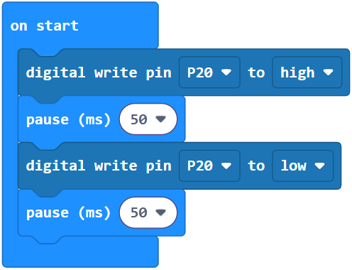
Try this: pin_20_blink_fast
You can change the light’s blink rate by changing the pause block’s ms argument. For example, to make the light blink a lot faster, significantly reduce the pause time.
- Rename the project pin_20_blink to pin_20_blink_fast or make a new one
- Change pause (2000) and pause (1000) to pause (50).
- Flash the project, then watch the LED located at P20 — is it blinking faster now?
Your turn
Expand your project to control the P21 light along with the P20 light.
- Modify your program so that it turns both lights on and off at about the same time.
- Modify your program so that whenever one light is on, the other is off.