Skip to content
Parallax Learn

Parallax Learn

  • Welcome
  • Tutorials
        • Tutorial Series head tag

          Tutorial Series
        • Tutorial Series

          The special, classroom-ready series pages are organized collections of tutorials for our most popular hardware and/or languages. The tutorials for each topic are conveniently accessible from a single page, shown in the order it is recommended that they be completed.
        • Robotics Series Head tag

          Robotics Series
        • Robotics Series

          • Artificial Intelligence
          • Cybersecurity: Radio Data tutorialCybersecurity
          • cyber:bot + Python
          • cyber:bot + MakeCode
          • Boe-Bot Tutorial SeriesBoe-Bot
          • Arduino Shield-Bot
          • ActivityBot with C TutorialsActivityBot + C
          • ActivityBot with BlocklyProp Tutorial SeriesActivityBot + BlocklyProp
          • Scribbler 3 Tutorial SeriesScribbler 3
        • Electronics & Programming Series Head tag

          Electronics & Programming Series
          • BS2 Board of Education Tutorial SeriesBS2 Board of Education
          • Propeller C-Language BasicsPropeller C Basics
          • FLiP Try-It Kit C Tutorial SeriesFLiP Try-It Kit + C
          • FLiP Try-It Kit BlocklyProp TutorialsFLiP Try-It Kit + BlocklyProp
          • Badge WX Tutorial SeriesBadge WX
          • Propeller BlocklyProp Basics and ProjectsPropeller BlocklyProp Basics
          • View All Tutorial Series »
        • Browse Tutorials
        • Browse Tutorials

          Individual tutorials sorted by robot or kit, and language.
        • By Robot or Kit
          • ActivityBot
          • SumoBot WX
          • Boe-Bot
          • Shield-Bot
          • cyber:bot
          • Badge WX
          • ELEV-8
          • ARLO
        • By Language
        • By Language

          • Propeller C
          • Arduino
          • BlocklyProp
          • PBASIC
          • Python
          • MakeCode
          • View All Tutorials »
  • Educators
  • Reference
  • Downloads
  • Home
  • All Courses

Robotics with the Board of Education Shield for Arduino

Curriculum

  • 9 Sections
  • 148 Lessons
  • Lifetime
Expand all sectionsCollapse all sections
  • About This Tutorial
    3
    • 2.0
      About the BOE Shield-Bot
    • 2.1
      Audience and Support
    • 2.2
      Author & Contributors
  • Chapter 1. Your Shield-Bot's Brain
    25
    • 3.1
      Chapter 1. Your Shield-Bot’s Brain
    • 3.2
      Hardware and Software Options
    • 3.3
      Shield-Bot Chassis Parts
    • 3.4
      Shield-Bot Hardware
    • 3.5
      Shield-Bot Electronics Parts
    • 3.6
      Activity 1: Download and Install the Software
    • 3.7
      Activity 2: Write a Simple “Hello!” Sketch
    • 3.8
      Codebender Hello Sketch
    • 3.9
      How the Hello Sketch Code Works
    • 3.10
      Modify the Sketch to Repeat
    • 3.11
      Hello Messages on New Lines
    • 3.12
      Open the Arduino Reference
    • 3.13
      Activity 3: Store and Retrieve Values
    • 3.14
      Global vs.Local Variables
    • 3.15
      Activity 4: Solve Math Problems
    • 3.16
      Try Floating Point Math
    • 3.17
      Activity 5: Make Decisions
    • 3.18
      More Decisions with if… else if
    • 3.19
      Activity 6: Count and Control Repetitions
    • 3.20
      How the for Loop Works
    • 3.21
      Adjust Initialization, Condition, and Increment
    • 3.22
      Activity 7: Constants and Comments
    • 3.23
      Chapter 1 Summary
    • 3.24
      Chapter 1 Challenges
    • 3.25
      Chapter 1 Solutions
  • Chapter 2. Shield, Lights, Servo Motors
    23
    • 4.0
      Chapter 2. Shield, Lights, Servo Motors
    • 4.1
      Activity 1: Board of Education Shield Setup
    • 4.2
      Activity 2: Build and Test LED Indicator Lights
    • 4.3
      Introducing the Resistor
    • 4.4
      Introducing the LED
    • 4.5
      Introducing the Prototyping Area
    • 4.6
      LED Test Circuit
    • 4.7
      How a Sketch Makes the LED Turn On and Off
    • 4.8
      Introducing the Timing Diagram
    • 4.9
      Activity 3: LED Servo Signal Monitors
    • 4.10
      How to Use the Arduino Servo Library
    • 4.11
      Activity 4: Connect Servo Motors and Batteries
    • 4.12
      Connect the Servos to the BOE Shield
    • 4.13
      Connect the Battery Pack to the BOE Shield
    • 4.14
      5-cell Pack Setup
    • 4.15
      4-cell Pack + Boe-Boost Setup
    • 4.16
      Activity 5: Centering the Servos
    • 4.17
      Activity 6: Testing the Servos
    • 4.18
      Controlling Servo Speed and Direction
    • 4.19
      How To Control Servo Run Time
    • 4.20
      Chapter 2 Summary
    • 4.21
      Chapter 2 Challenges
    • 4.22
      Chapter 2 Solutions
  • Chapter 3. Assemble and Test your BOE Shield-Bot
    22
    • 5.0
      Chapter 3. Assemble and Test your BOE Shield-Bot
    • 5.1
      Activity 1: Assembling the BOE-Shield-Bot
    • 5.2
      Mount the Topside Hardware
    • 5.3
      Remove the Servo Horns
    • 5.4
      Mount the Servos on the Chassis
    • 5.5
      Mount the Battery Pack
    • 5.6
      Mount the Wheels
    • 5.7
      Attach the BOE Shield to the Chassis
    • 5.8
      Activity 2: Re-test the Servos
    • 5.9
      Testing the Left and Right Wheels
    • 5.10
      Servo Troubleshooting
    • 5.11
      Activity 3: Start-Reset Indicator
    • 5.12
      Build the Piezospeaker Circuit
    • 5.13
      Programming the Start-Reset Indicator
    • 5.14
      Example Sketch: StartResetIndicator
    • 5.15
      Activity 4: Test Speed Control
    • 5.16
      Example Sketch: Test Servo Speed
    • 5.17
      How TestServoSpeed Works
    • 5.18
      Optional: Record Your Own Transfer Curve Data
    • 5.19
      Chapter 3 Summary
    • 5.20
      Chapter 3 Challenges
    • 5.21
      Chapter 3 Solutions
  • Chapter 4. BOE Shield-Bot Navigation
    19
    • 6.0
      Chapter 4. BOE Shield-Bot Navigation
    • 6.1
      Activity 1: Basic BOE Shield-Bot Maneuvers
    • 6.2
      How ForwardThreeSeconds Works
    • 6.3
      Moving Backward, Rotating, and Pivoting
    • 6.4
      Activity 2: Tuning the Basic Maneuvers
    • 6.5
      Tuning the Turns
    • 6.6
      Activity 3: Calculating Distances
    • 6.7
      Activity 4: Ramping Maneuvers
    • 6.8
      Activity 5: Simplify Navigation with Functions
    • 6.9
      Function Call with Parameters
    • 6.10
      Put Maneuvers Into Functions
    • 6.11
      Activity 6: Custom Maneuver Function
    • 6.12
      Activity 7: Maneuver Sequences with Arrays
    • 6.13
      Using Array Elements
    • 6.14
      Navigation with Arrays
    • 6.15
      Character Arrays and switch-case
    • 6.16
      Chapter 4 Summary
    • 6.17
      Chapter 4 Challenges
    • 6.18
      Chapter 4 Solutions
  • Chapter 5. Tactile Navigation with Whiskers
    13
    • 7.0
      Chapter 5. Tactile Navigation with Whiskers
    • 7.1
      Activity 1: Build and Test the Whiskers
    • 7.2
      How Whisker Switches Work
    • 7.3
      Testing the Whiskers
    • 7.4
      How DisplayWhiskerStates Works
    • 7.5
      Activity 2: Field-Test the Whiskers
    • 7.6
      Activity 3: Navigation with Whiskers
    • 7.7
      How RoamingWithWhiskers Works
    • 7.8
      Activity 4: Artificial Intelligence for Escaping Corners
    • 7.9
      How Escaping Corners Works
    • 7.10
      Chapter 5 Summary
    • 7.11
      Chapter 5 Challenges
    • 7.12
      Chapter 5 Solutions
  • Chapter 6. Light-Sensitive Navigation with Phototransistors
    18
    • 8.0
      Chapter 6. Light-Sensitive Navigation with Phototransistors
    • 8.1
      Introducing the Phototransistor
    • 8.2
      Activity 1: Simple Light to Voltage Sensor
    • 8.3
      Example Sketch: PhototransistorVoltage
    • 8.4
      Halt Under the Bright Light
    • 8.5
      How the Phototransistor Circuit Works
    • 8.6
      Ohm’s Law
    • 8.7
      Activity 2: Measure Light Levels Over a Larger Range
    • 8.8
      Building the Photosensitive Eyes
    • 8.9
      Test the Phototransistor Circuit
    • 8.10
      rcTime and Voltage Decay
    • 8.11
      Activity 3: Light Measurements for Roaming
    • 8.12
      Light Measurement Graphic Display
    • 8.13
      Activity 4: Test a Light-Roaming Routine
    • 8.14
      Activity 5: Shield-Bot Navigating by Light
    • 8.15
      Chapter 6 Summary
    • 8.16
      Chapter 6 Challenges
    • 8.17
      Chapter 6 Solutions
  • Chapter 7. Navigating with Infrared Headlights
    14
    • 9.0
      Chapter 7. Navigating with Infrared Headlights
    • 9.1
      Infrared Light Signals
    • 9.2
      Activity 1: Build and Test the Object Detectors
    • 9.3
      Object Detection Test Code
    • 9.4
      Activity 2: Field Testing
    • 9.5
      Sniffing for IR Interference
    • 9.6
      Activty 3: Detection Range Adjustments
    • 9.7
      Activity 4: Object Detection and Avoidance
    • 9.8
      Activity 5: High-performance IR Navigation
    • 9.9
      Activity 6: Drop-off Detector
    • 9.10
      Example Sketch: AvoidTableEdge
    • 9.11
      Chapter 7 Summary
    • 9.12
      Chapter 7 Challenges
    • 9.13
      Chapter 7 Solutions
  • Chapter 8. Robot Control with Distance Detection
    11
    • 10.0
      Chapter 8. Robot Control with Distance Detection
    • 10.1
      Activity 1: Testing the Frequency Sweep
    • 10.2
      Displaying Both Distances
    • 10.3
      Activity 2: BOE Shield-Bot Shadow Vehicle
    • 10.4
      A Look Inside Proportional Control
    • 10.5
      Example Sketch: FollowingShieldBot
    • 10.6
      Follow the Leader
    • 10.7
      Activity 3: What’s Next?
    • 10.8
      Chapter 8 Summary
    • 10.9
      Chapter 8 Challenges
    • 10.10
      Chapter 8 Solutions

Activity 6: Testing the Servos

There’s one last thing to do before assembling your BOE Shield-Bot, and that’s testing the servos.  In this activity, you will run sketches that make the servos turn at different speeds and directions.  This is an example of subsystem testing—a good habit to develop.

Subsystem testing is the practice of testing the individual components before they go into the larger device.  It’s a valuable strategy that can help you win robotics contests.  It’s also an essential skill used by engineers to develop everything from toys, cars, and video games to space shuttles and Mars roving robots.  Especially in more complex devices, it can become nearly impossible to figure out a problem if the individual components haven’t been tested beforehand.  In aerospace projects, for example, disassembling a prototype to fix a problem can cost hundreds of thousands, or even millions, of dollars.  In those kinds of projects, subsystem testing is rigorous and thorough.

Pulse Width Controls Speed and Direction

This timing diagram shows how a Parallax continuous rotation servo turns full speed clockwise when you send it 1.3 ms pulses.  Full speed typically falls in the 50 to 60 RPM range.

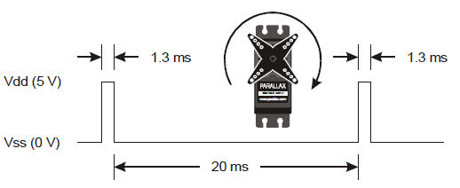
What’s RPM?  Revolutions Per Minute—the number of full rotations turned in one minute.

What’s a pulse train?  Just as a railroad train is a series of cars, a pulse train is a series of pulses (brief high signals).

Example Sketch: LeftServoClockwise

  • Enter, save, and upload LeftServoClockwise.
  • Verify that the servo’s horn is rotating between 50 and 60 RPM clockwise.
/*
 Robotics with the BOE Shield – LeftServoClockwise
 Generate a servo full speed clockwise signal on digital pin 13.
 */

#include <Servo.h>                           // Include servo library
 
Servo servoLeft;                             // Declare left servo

void setup()                                 // Built in initialization block
{
  servoLeft.attach(13);                      // Attach left signal to pin 13
  servoLeft.writeMicroseconds(1300);         // 1.3 ms full speed clockwise
}  
 
void loop()                                  // Main loop auto-repeats
{                                            // Empty, nothing needs repeating
}

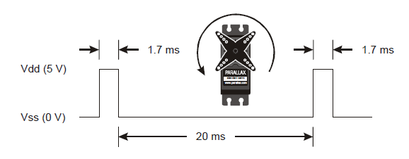
Your Turn: Left Servo Counterclockwise

  • Save LeftServoClockwise as LeftServoCounterclockwise.
  • In servoLeft.writeMicroseconds, change (1300) to (1700).
  • Save the modified sketch and upload it to the Arduino.
  • Verify that the servo connected to pin 13 now rotates the other direction, which should be counterclockwise, at about 50 to 60 RPM.

Example Sketch: RightServoClockwise

  • Save LeftServoClockwise as RightServoClockwise.
  • Replace all instances of servoLeft with servoRight.
  • Replace all instance of 13 with 12.
  • Run the sketch and verify that the pin 12 servo is rotating between 50 and 60 RPM clockwise.
/*
 Robotics with the BOE Shield – RightServoClockwise
 Generate a servo full speed clockwise signal on digital pin 12.
 */

#include <Servo.h>                           // Include servo library
 
Servo servoRight;                            // Declare left servo

void setup()                                 // Built in initialization block
{
  servoRight.attach(12);                     // Attach left signal to pin 12
  servoRight.writeMicroseconds(1300);        // 1.3 ms full speed clockwise
}  
 
void loop()                                  // Main loop auto-repeats
{                                            // Empty, nothing needs repeating
}

Your Turn – Right Servo Counterclockwise

  • In servoRight.writeMicroseconds change (1300) to (1700).
  • Save the sketch and upload it to your Arduino.
  • Verify that the pin 12 servo turns full-speed counterclockwise, about 50 to 60 RPM.

Printer-friendly version
Activity 5: Centering the Servos
Prev
Controlling Servo Speed and Direction
Next

DISCUSSION FORUMS | PARALLAX INC. STORE

About | Terms of Use | Feedback: learn@parallax.com | Copyright©Parallax Inc. 2024

© 2026 Parallax Learn • Built with GeneratePress