Skip to content
Parallax Learn

Parallax Learn

  • Welcome
  • Tutorials
        • Tutorial Series head tag

          Tutorial Series
        • Tutorial Series

          The special, classroom-ready series pages are organized collections of tutorials for our most popular hardware and/or languages. The tutorials for each topic are conveniently accessible from a single page, shown in the order it is recommended that they be completed.
        • Robotics Series Head tag

          Robotics Series
        • Robotics Series

          • Artificial Intelligence
          • Cybersecurity: Radio Data tutorialCybersecurity
          • cyber:bot + Python
          • cyber:bot + MakeCode
          • Boe-Bot Tutorial SeriesBoe-Bot
          • Arduino Shield-Bot
          • ActivityBot with C TutorialsActivityBot + C
          • ActivityBot with BlocklyProp Tutorial SeriesActivityBot + BlocklyProp
          • Scribbler 3 Tutorial SeriesScribbler 3
        • Electronics & Programming Series Head tag

          Electronics & Programming Series
          • BS2 Board of Education Tutorial SeriesBS2 Board of Education
          • Propeller C-Language BasicsPropeller C Basics
          • FLiP Try-It Kit C Tutorial SeriesFLiP Try-It Kit + C
          • FLiP Try-It Kit BlocklyProp TutorialsFLiP Try-It Kit + BlocklyProp
          • Badge WX Tutorial SeriesBadge WX
          • Propeller BlocklyProp Basics and ProjectsPropeller BlocklyProp Basics
          • View All Tutorial Series »
        • Browse Tutorials
        • Browse Tutorials

          Individual tutorials sorted by robot or kit, and language.
        • By Robot or Kit
          • ActivityBot
          • SumoBot WX
          • Boe-Bot
          • Shield-Bot
          • cyber:bot
          • Badge WX
          • ELEV-8
          • ARLO
        • By Language
        • By Language

          • Propeller C
          • Arduino
          • BlocklyProp
          • PBASIC
          • Python
          • MakeCode
          • View All Tutorials »
  • Educators
  • Reference
  • Downloads
  • Home
  • All Courses

Robotics with the Board of Education Shield for Arduino

Curriculum

  • 9 Sections
  • 148 Lessons
  • Lifetime
Expand all sectionsCollapse all sections
  • About This Tutorial
    3
    • 1.1
      About the BOE Shield-Bot
    • 1.2
      Audience and Support
    • 1.3
      Author & Contributors
  • Chapter 1. Your Shield-Bot's Brain
    25
    • 2.1
      Chapter 1. Your Shield-Bot’s Brain
    • 2.2
      Hardware and Software Options
    • 2.3
      Shield-Bot Chassis Parts
    • 2.4
      Shield-Bot Hardware
    • 2.5
      Shield-Bot Electronics Parts
    • 2.6
      Activity 1: Download and Install the Software
    • 2.7
      Activity 2: Write a Simple “Hello!” Sketch
    • 2.8
      Codebender Hello Sketch
    • 2.9
      How the Hello Sketch Code Works
    • 2.10
      Modify the Sketch to Repeat
    • 2.11
      Hello Messages on New Lines
    • 2.12
      Open the Arduino Reference
    • 2.13
      Activity 3: Store and Retrieve Values
    • 2.14
      Global vs. Local Variables
    • 2.15
      Activity 4: Solve Math Problems
    • 2.16
      Try Floating Point Math
    • 2.17
      Activity 5: Make Decisions
    • 2.18
      More Decisions with if… else if
    • 2.19
      Activity 6: Count and Control Repetitions
    • 2.20
      How the for Loop Works
    • 2.21
      Adjust Initialization, Condition, and Increment
    • 2.22
      Activity 7: Constants and Comments
    • 2.23
      Chapter 1 Summary
    • 2.24
      Chapter 1 Challenges
    • 2.25
      Chapter 1 Solutions
  • Chapter 2. Shield, Lights, Servo Motors
    23
    • 3.1
      Chapter 2. Shield, Lights, Servo Motors
    • 3.2
      Activity 1: Board of Education Shield Setup
    • 3.3
      Activity 2: Build and Test LED Indicator Lights
    • 3.4
      Introducing the Resistor
    • 3.5
      Introducing the LED
    • 3.6
      Introducing the Prototyping Area
    • 3.7
      LED Test Circuit
    • 3.8
      How a Sketch Makes the LED Turn On and Off
    • 3.9
      Introducing the Timing Diagram
    • 3.10
      Activity 3: LED Servo Signal Monitors
    • 3.11
      How to Use the Arduino Servo Library
    • 3.12
      Activity 4: Connect Servo Motors and Batteries
    • 3.13
      Connect the Servos to the BOE Shield
    • 3.14
      Connect the Battery Pack to the BOE Shield
    • 3.15
      5-cell Pack Setup
    • 3.16
      4-cell Pack + Boe-Boost Setup
    • 3.17
      Activity 5: Centering the Servos
    • 3.18
      Activity 6: Testing the Servos
    • 3.19
      Controlling Servo Speed and Direction
    • 3.20
      How To Control Servo Run Time
    • 3.21
      Chapter 2 Summary
    • 3.22
      Chapter 2 Challenges
    • 3.23
      Chapter 2 Solutions
  • Chapter 3. Assemble and Test your BOE Shield-Bot
    22
    • 4.1
      Chapter 3. Assemble and Test your BOE Shield-Bot
    • 4.2
      Activity 1: Assembling the BOE-Shield-Bot
    • 4.3
      Mount the Topside Hardware
    • 4.4
      Remove the Servo Horns
    • 4.5
      Mount the Servos on the Chassis
    • 4.6
      Mount the Battery Pack
    • 4.7
      Mount the Wheels
    • 4.8
      Attach the BOE Shield to the Chassis
    • 4.9
      Activity 2: Re-test the Servos
    • 4.10
      Testing the Left and Right Wheels
    • 4.11
      Servo Troubleshooting
    • 4.12
      Activity 3: Start-Reset Indicator
    • 4.13
      Build the Piezospeaker Circuit
    • 4.14
      Programming the Start-Reset Indicator
    • 4.15
      Example Sketch: StartResetIndicator
    • 4.16
      Activity 4: Test Speed Control
    • 4.17
      Example Sketch: Test Servo Speed
    • 4.18
      How TestServoSpeed Works
    • 4.19
      Optional: Record Your Own Transfer Curve Data
    • 4.20
      Chapter 3 Summary
    • 4.21
      Chapter 3 Challenges
    • 4.22
      Chapter 3 Solutions
  • Chapter 4. BOE Shield-Bot Navigation
    19
    • 5.1
      Chapter 4. BOE Shield-Bot Navigation
    • 5.2
      Activity 1: Basic BOE Shield-Bot Maneuvers
    • 5.3
      How ForwardThreeSeconds Works
    • 5.4
      Moving Backward, Rotating, and Pivoting
    • 5.5
      Activity 2: Tuning the Basic Maneuvers
    • 5.6
      Tuning the Turns
    • 5.7
      Activity 3: Calculating Distances
    • 5.8
      Activity 4: Ramping Maneuvers
    • 5.9
      Activity 5: Simplify Navigation with Functions
    • 5.10
      Function Call with Parameters
    • 5.11
      Put Maneuvers Into Functions
    • 5.12
      Activity 6: Custom Maneuver Function
    • 5.13
      Activity 7: Maneuver Sequences with Arrays
    • 5.14
      Using Array Elements
    • 5.15
      Navigation with Arrays
    • 5.16
      Character Arrays and switch-case
    • 5.17
      Chapter 4 Summary
    • 5.18
      Chapter 4 Challenges
    • 5.19
      Chapter 4 Solutions
  • Chapter 5. Tactile Navigation with Whiskers
    13
    • 6.1
      Chapter 5. Tactile Navigation with Whiskers
    • 6.2
      Activity 1: Build and Test the Whiskers
    • 6.3
      How Whisker Switches Work
    • 6.4
      Testing the Whiskers
    • 6.5
      How DisplayWhiskerStates Works
    • 6.6
      Activity 2: Field-Test the Whiskers
    • 6.7
      Activity 3: Navigation with Whiskers
    • 6.8
      How RoamingWithWhiskers Works
    • 6.9
      Activity 4: Artificial Intelligence for Escaping Corners
    • 6.10
      How Escaping Corners Works
    • 6.11
      Chapter 5 Summary
    • 6.12
      Chapter 5 Challenges
    • 6.13
      Chapter 5 Solutions
  • Chapter 6. Light-Sensitive Navigation with Phototransistors
    18
    • 7.1
      Chapter 6. Light-Sensitive Navigation with Phototransistors
    • 7.2
      Introducing the Phototransistor
    • 7.3
      Activity 1: Simple Light to Voltage Sensor
    • 7.4
      Example Sketch: PhototransistorVoltage
    • 7.5
      Halt Under the Bright Light
    • 7.6
      How the Phototransistor Circuit Works
    • 7.7
      Ohm’s Law
    • 7.8
      Activity 2: Measure Light Levels Over a Larger Range
    • 7.9
      Building the Photosensitive Eyes
    • 7.10
      Test the Phototransistor Circuit
    • 7.11
      rcTime and Voltage Decay
    • 7.12
      Activity 3: Light Measurements for Roaming
    • 7.13
      Light Measurement Graphic Display
    • 7.14
      Activity 4: Test a Light-Roaming Routine
    • 7.15
      Activity 5: Shield-Bot Navigating by Light
    • 7.16
      Chapter 6 Summary
    • 7.17
      Chapter 6 Challenges
    • 7.18
      Chapter 6 Solutions
  • Chapter 7. Navigating with Infrared Headlights
    14
    • 8.1
      Chapter 7. Navigating with Infrared Headlights
    • 8.2
      Infrared Light Signals
    • 8.3
      Activity 1: Build and Test the Object Detectors
    • 8.4
      Object Detection Test Code
    • 8.5
      Activity 2: Field Testing
    • 8.6
      Sniffing for IR Interference
    • 8.7
      Activty 3: Detection Range Adjustments
    • 8.8
      Activity 4: Object Detection and Avoidance
    • 8.9
      Activity 5: High-performance IR Navigation
    • 8.10
      Activity 6: Drop-off Detector
    • 8.11
      Example Sketch: AvoidTableEdge
    • 8.12
      Chapter 7 Summary
    • 8.13
      Chapter 7 Challenges
    • 8.14
      Chapter 7 Solutions
  • Chapter 8. Robot Control with Distance Detection
    11
    • 9.1
      Chapter 8. Robot Control with Distance Detection
    • 9.2
      Activity 1: Testing the Frequency Sweep
    • 9.3
      Displaying Both Distances
    • 9.4
      Activity 2: BOE Shield-Bot Shadow Vehicle
    • 9.5
      A Look Inside Proportional Control
    • 9.6
      Example Sketch: FollowingShieldBot
    • 9.7
      Follow the Leader
    • 9.8
      Activity 3: What’s Next?
    • 9.9
      Chapter 8 Summary
    • 9.10
      Chapter 8 Challenges
    • 9.11
      Chapter 8 Solutions

Testing the Whiskers

The next sketch tests the whiskers to make sure they are functioning properly, by displaying the binary values returned by digitalRead(7) and digitalRead(5).  This way, you can press each whisker against its 3-pin header on the breadboard, and see if the Arduino’s digital pin is sensing the electrical contact.   

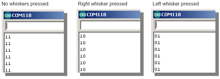
When neither whisker is pressed up against its 3-pin header, you can expect your Serial Monitor to display two columns of 1’s, one for each whisker. If you press just the right whisker, the right column should report 0, and the display should read 10.  If you press just the left whisker, the left column should report 1 and the display should read 01.  Of course, if you press both whiskers, it should display 00.

Active-low Output
The whisker circuits are wired for active-low output, which means that they each send a low signal when they are pressed (active) and a high signal when they are not pressed.  Since digitalRead returns 0 for a low signal and 1 for a high signal, 0 is what tells your sketch that a whisker is pressed, and 1 tells it that a whisker is not pressed.

  • Enter, save, and upload TestWhiskers to your Arduino.
  • Reconnect the USB cable and set the 3-position switch to position 1.
  • As soon as the sketch is finished uploading, open the Serial Monitor.
  • Leave the USB cable connected so that the Arduino can send serial messages to the Serial Monitor.

Example Sketch: DisplayWhiskerStates

/*
 * Robotics with the BOE Shield - DisplayWhiskerStates
 * Display left and right whisker states in Serial Monitor.
 * 1 indicates no contact; 0 indicates contact.
 */

void setup()                                 // Built-in initialization block
{
  tone(4, 3000, 1000);                       // Play tone for 1 second
  delay(1000);                               // Delay to finish tone
  pinMode(7, INPUT);                         // Set right whisker pin to input
  pinMode(5, INPUT);                         // Set left whisker pin to input  

  Serial.begin(9600);                        // Set data rate to 9600 bps
}  
 
void loop()                                  // Main loop auto-repeats
{                                            
  byte wLeft = digitalRead(5);               // Copy left result to wLeft  
  byte wRight = digitalRead(7);              // Copy right result to wRight

  Serial.print(wLeft);                       // Display left whisker state
  Serial.println(wRight);                    // Display right whisker state

  delay(50);                                 // Pause for 50 ms
}    
  • Look at the values displayed in the Serial Monitor.  With no whiskers pressed, it should display 11, indicating 5 V is applied to both digital inputs (5 and 7).
  • Press the right whisker into its three-pin header, and note the values displayed in the Serial Monitor.  It should now read 10.
  • Release the right whisker and press the left whisker into its three-pin header, and note the value displayed in the Serial Monitor again.  This time it should read 01.
  • Press both whiskers against both three-pin headers.  Now it should read 00.
  • If the whiskers passed all these tests, you’re ready to move on.  If not, check your sketch and circuits for errors.

These steps are important!  
Seriously, you’ve got to make sure your circuit and code pass these tests before continuing.  The rest of the examples in this chapter rely on the whiskers working correctly.  If you haven’t tested and corrected any errors, the rest of the examples won’t work right.


Printer-friendly version
How Whisker Switches Work
Prev
How DisplayWhiskerStates Works
Next

DISCUSSION FORUMS | PARALLAX INC. STORE

About | Terms of Use | Feedback: learn@parallax.com | Copyright©Parallax Inc. 2024

© 2026 Parallax Learn • Built with GeneratePress