Skip to content
Parallax Learn

Parallax Learn

  • Welcome
  • Tutorials
        • Tutorial Series head tag

          Tutorial Series
        • Tutorial Series

          The special, classroom-ready series pages are organized collections of tutorials for our most popular hardware and/or languages. The tutorials for each topic are conveniently accessible from a single page, shown in the order it is recommended that they be completed.
        • Robotics Series Head tag

          Robotics Series
        • Robotics Series

          • Artificial Intelligence
          • Cybersecurity: Radio Data tutorialCybersecurity
          • cyber:bot + Python
          • cyber:bot + MakeCode
          • Boe-Bot Tutorial SeriesBoe-Bot
          • Arduino Shield-Bot
          • ActivityBot with C TutorialsActivityBot + C
          • ActivityBot with BlocklyProp Tutorial SeriesActivityBot + BlocklyProp
          • Scribbler 3 Tutorial SeriesScribbler 3
        • Electronics & Programming Series Head tag

          Electronics & Programming Series
          • BS2 Board of Education Tutorial SeriesBS2 Board of Education
          • Propeller C-Language BasicsPropeller C Basics
          • FLiP Try-It Kit C Tutorial SeriesFLiP Try-It Kit + C
          • FLiP Try-It Kit BlocklyProp TutorialsFLiP Try-It Kit + BlocklyProp
          • Badge WX Tutorial SeriesBadge WX
          • Propeller BlocklyProp Basics and ProjectsPropeller BlocklyProp Basics
          • View All Tutorial Series »
        • Browse Tutorials
        • Browse Tutorials

          Individual tutorials sorted by robot or kit, and language.
        • By Robot or Kit
          • ActivityBot
          • SumoBot WX
          • Boe-Bot
          • Shield-Bot
          • cyber:bot
          • Badge WX
          • ELEV-8
          • ARLO
        • By Language
        • By Language

          • Propeller C
          • Arduino
          • BlocklyProp
          • PBASIC
          • Python
          • MakeCode
          • View All Tutorials »
  • Educators
  • Reference
  • Downloads
  • Home
  • All Courses

Robotics with the Board of Education Shield for Arduino

Curriculum

  • 9 Sections
  • 148 Lessons
  • Lifetime
Expand all sectionsCollapse all sections
  • About This Tutorial
    3
    • 2.0
      About the BOE Shield-Bot
    • 2.1
      Audience and Support
    • 2.2
      Author & Contributors
  • Chapter 1. Your Shield-Bot's Brain
    25
    • 3.1
      Chapter 1. Your Shield-Bot’s Brain
    • 3.2
      Hardware and Software Options
    • 3.3
      Shield-Bot Chassis Parts
    • 3.4
      Shield-Bot Hardware
    • 3.5
      Shield-Bot Electronics Parts
    • 3.6
      Activity 1: Download and Install the Software
    • 3.7
      Activity 2: Write a Simple “Hello!” Sketch
    • 3.8
      Codebender Hello Sketch
    • 3.9
      How the Hello Sketch Code Works
    • 3.10
      Modify the Sketch to Repeat
    • 3.11
      Hello Messages on New Lines
    • 3.12
      Open the Arduino Reference
    • 3.13
      Activity 3: Store and Retrieve Values
    • 3.14
      Global vs.Local Variables
    • 3.15
      Activity 4: Solve Math Problems
    • 3.16
      Try Floating Point Math
    • 3.17
      Activity 5: Make Decisions
    • 3.18
      More Decisions with if… else if
    • 3.19
      Activity 6: Count and Control Repetitions
    • 3.20
      How the for Loop Works
    • 3.21
      Adjust Initialization, Condition, and Increment
    • 3.22
      Activity 7: Constants and Comments
    • 3.23
      Chapter 1 Summary
    • 3.24
      Chapter 1 Challenges
    • 3.25
      Chapter 1 Solutions
  • Chapter 2. Shield, Lights, Servo Motors
    23
    • 4.0
      Chapter 2. Shield, Lights, Servo Motors
    • 4.1
      Activity 1: Board of Education Shield Setup
    • 4.2
      Activity 2: Build and Test LED Indicator Lights
    • 4.3
      Introducing the Resistor
    • 4.4
      Introducing the LED
    • 4.5
      Introducing the Prototyping Area
    • 4.6
      LED Test Circuit
    • 4.7
      How a Sketch Makes the LED Turn On and Off
    • 4.8
      Introducing the Timing Diagram
    • 4.9
      Activity 3: LED Servo Signal Monitors
    • 4.10
      How to Use the Arduino Servo Library
    • 4.11
      Activity 4: Connect Servo Motors and Batteries
    • 4.12
      Connect the Servos to the BOE Shield
    • 4.13
      Connect the Battery Pack to the BOE Shield
    • 4.14
      5-cell Pack Setup
    • 4.15
      4-cell Pack + Boe-Boost Setup
    • 4.16
      Activity 5: Centering the Servos
    • 4.17
      Activity 6: Testing the Servos
    • 4.18
      Controlling Servo Speed and Direction
    • 4.19
      How To Control Servo Run Time
    • 4.20
      Chapter 2 Summary
    • 4.21
      Chapter 2 Challenges
    • 4.22
      Chapter 2 Solutions
  • Chapter 3. Assemble and Test your BOE Shield-Bot
    22
    • 5.0
      Chapter 3. Assemble and Test your BOE Shield-Bot
    • 5.1
      Activity 1: Assembling the BOE-Shield-Bot
    • 5.2
      Mount the Topside Hardware
    • 5.3
      Remove the Servo Horns
    • 5.4
      Mount the Servos on the Chassis
    • 5.5
      Mount the Battery Pack
    • 5.6
      Mount the Wheels
    • 5.7
      Attach the BOE Shield to the Chassis
    • 5.8
      Activity 2: Re-test the Servos
    • 5.9
      Testing the Left and Right Wheels
    • 5.10
      Servo Troubleshooting
    • 5.11
      Activity 3: Start-Reset Indicator
    • 5.12
      Build the Piezospeaker Circuit
    • 5.13
      Programming the Start-Reset Indicator
    • 5.14
      Example Sketch: StartResetIndicator
    • 5.15
      Activity 4: Test Speed Control
    • 5.16
      Example Sketch: Test Servo Speed
    • 5.17
      How TestServoSpeed Works
    • 5.18
      Optional: Record Your Own Transfer Curve Data
    • 5.19
      Chapter 3 Summary
    • 5.20
      Chapter 3 Challenges
    • 5.21
      Chapter 3 Solutions
  • Chapter 4. BOE Shield-Bot Navigation
    19
    • 6.0
      Chapter 4. BOE Shield-Bot Navigation
    • 6.1
      Activity 1: Basic BOE Shield-Bot Maneuvers
    • 6.2
      How ForwardThreeSeconds Works
    • 6.3
      Moving Backward, Rotating, and Pivoting
    • 6.4
      Activity 2: Tuning the Basic Maneuvers
    • 6.5
      Tuning the Turns
    • 6.6
      Activity 3: Calculating Distances
    • 6.7
      Activity 4: Ramping Maneuvers
    • 6.8
      Activity 5: Simplify Navigation with Functions
    • 6.9
      Function Call with Parameters
    • 6.10
      Put Maneuvers Into Functions
    • 6.11
      Activity 6: Custom Maneuver Function
    • 6.12
      Activity 7: Maneuver Sequences with Arrays
    • 6.13
      Using Array Elements
    • 6.14
      Navigation with Arrays
    • 6.15
      Character Arrays and switch-case
    • 6.16
      Chapter 4 Summary
    • 6.17
      Chapter 4 Challenges
    • 6.18
      Chapter 4 Solutions
  • Chapter 5. Tactile Navigation with Whiskers
    13
    • 7.0
      Chapter 5. Tactile Navigation with Whiskers
    • 7.1
      Activity 1: Build and Test the Whiskers
    • 7.2
      How Whisker Switches Work
    • 7.3
      Testing the Whiskers
    • 7.4
      How DisplayWhiskerStates Works
    • 7.5
      Activity 2: Field-Test the Whiskers
    • 7.6
      Activity 3: Navigation with Whiskers
    • 7.7
      How RoamingWithWhiskers Works
    • 7.8
      Activity 4: Artificial Intelligence for Escaping Corners
    • 7.9
      How Escaping Corners Works
    • 7.10
      Chapter 5 Summary
    • 7.11
      Chapter 5 Challenges
    • 7.12
      Chapter 5 Solutions
  • Chapter 6. Light-Sensitive Navigation with Phototransistors
    18
    • 8.0
      Chapter 6. Light-Sensitive Navigation with Phototransistors
    • 8.1
      Introducing the Phototransistor
    • 8.2
      Activity 1: Simple Light to Voltage Sensor
    • 8.3
      Example Sketch: PhototransistorVoltage
    • 8.4
      Halt Under the Bright Light
    • 8.5
      How the Phototransistor Circuit Works
    • 8.6
      Ohm’s Law
    • 8.7
      Activity 2: Measure Light Levels Over a Larger Range
    • 8.8
      Building the Photosensitive Eyes
    • 8.9
      Test the Phototransistor Circuit
    • 8.10
      rcTime and Voltage Decay
    • 8.11
      Activity 3: Light Measurements for Roaming
    • 8.12
      Light Measurement Graphic Display
    • 8.13
      Activity 4: Test a Light-Roaming Routine
    • 8.14
      Activity 5: Shield-Bot Navigating by Light
    • 8.15
      Chapter 6 Summary
    • 8.16
      Chapter 6 Challenges
    • 8.17
      Chapter 6 Solutions
  • Chapter 7. Navigating with Infrared Headlights
    14
    • 9.0
      Chapter 7. Navigating with Infrared Headlights
    • 9.1
      Infrared Light Signals
    • 9.2
      Activity 1: Build and Test the Object Detectors
    • 9.3
      Object Detection Test Code
    • 9.4
      Activity 2: Field Testing
    • 9.5
      Sniffing for IR Interference
    • 9.6
      Activty 3: Detection Range Adjustments
    • 9.7
      Activity 4: Object Detection and Avoidance
    • 9.8
      Activity 5: High-performance IR Navigation
    • 9.9
      Activity 6: Drop-off Detector
    • 9.10
      Example Sketch: AvoidTableEdge
    • 9.11
      Chapter 7 Summary
    • 9.12
      Chapter 7 Challenges
    • 9.13
      Chapter 7 Solutions
  • Chapter 8. Robot Control with Distance Detection
    11
    • 10.0
      Chapter 8. Robot Control with Distance Detection
    • 10.1
      Activity 1: Testing the Frequency Sweep
    • 10.2
      Displaying Both Distances
    • 10.3
      Activity 2: BOE Shield-Bot Shadow Vehicle
    • 10.4
      A Look Inside Proportional Control
    • 10.5
      Example Sketch: FollowingShieldBot
    • 10.6
      Follow the Leader
    • 10.7
      Activity 3: What’s Next?
    • 10.8
      Chapter 8 Summary
    • 10.9
      Chapter 8 Challenges
    • 10.10
      Chapter 8 Solutions

Displaying Both Distances

It’s important to test that the detection distances are roughly the same for both IR LED/receiver pairs.  They don’t have to be identical, but if they are too far apart, the BOE Shield-Bot might have difficulty following an object in front of it because it will keep trying to turn to one side.  More subsystem testing!

A common cause of mismatched distance measurement is mismatched resistors used with the IR LEDs.  For example, if one side’s IR LED has a 1 kΩ resistor and the other has a 2 kΩ resistor, one side will need objects to be much closer to see them.  Another possibility, though rare, is that one IR detector is far more sensitive than the other. In that case, a larger resistor can be used in series with the IR LED on that side to make its IR headlight dimmer and correct the mismatched measurements.

Example Sketch – DisplayBothDistances

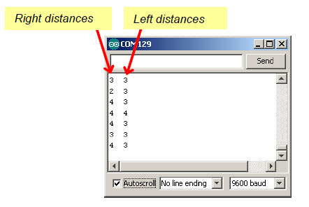
This screencapture shows some detection zone measurements from DisplayBothDistances in the Serial Monitor.  Though there’s fluctuation in the values, commonly called noise, what matters is that the numbers match, or are off by only 1, in each pair of measurements.

  • Enter, save, and upload DisplayBothDistances to your Arduino.
  • Use a box, book, bottle, or similar object as a target for the left distance detector.
  • Start by moving the object toward and away from the BOE Shield-Bot until you find the small range where a small movement will result in a change in distance measurement.
  • Find and record the midpoint of each distance detection zone.
  • Repeat for the right IR detector. 
  • If it turns out that the detection range of one side is twice as far as the other (or more), check the resistors connected to the IR LEDs.  You may have a mismatch there; make sure both resistors are 2 kΩ (red-black-red).  If there isn’t a mismatch, try adjusting IR LED resistor values until the detection ranges of both sides are in the same neighborhood.
/*
 * Robotics with the BOE Shield - DisplayBothDistances
 * Display left and right IR states in Serial Monitor.
 * Distance range is from 0 to 5.  Only a small range of several centimeters  
 * in front of each detector is measureable.  Most of it will be 0 (too 
 * close) or 5 (too far).
 */

void setup()                                 // Built-in initialization block
{
  tone(4, 3000, 1000);                       // Play tone for 1 second
  delay(1000);                               // Delay to finish tone

  pinMode(10, INPUT);  pinMode(9, OUTPUT);   // Left IR LED & Receiver
  pinMode(3, INPUT);  pinMode(2, OUTPUT);    // Right IR LED & Receiver

  Serial.begin(9600);                        // Set data rate to 9600 bps
}  
 
void loop()                                  // Main loop auto-repeats
{
  int irLeft = irDistance(9, 10);            // Measure left distance
  int irRight = irDistance(2, 3);            // Measure right distance

  Serial.print(irLeft);                      // Display left distance
  Serial.print("  ");                        // Display spaces
  Serial.println(irRight);                   // Display right distance

  delay(100);                                // 0.1 second delay
}

// IR distance measurement function

int irDistance(int irLedPin, int irReceivePin)
{  
  int distance = 0;
  for(long f = 38000; f <= 42000; f += 1000) {
    distance += irDetect(irLedPin, irReceivePin, f);
  }
  return distance;
}

// IR Detection function

int irDetect(int irLedPin, int irReceiverPin, long frequency)
{
  tone(irLedPin, frequency, 8);              // IRLED 38 kHz for at least 1 ms
  delay(1);                                  // Wait 1 ms
  int ir = digitalRead(irReceiverPin);       // IR receiver -> ir variable
  delay(1);                                  // Down time before recheck
  return ir;                                 // Return 1 no detect, 0 detect
}     

Your Turn – More Distance Tests

  • Try measuring the detection range for objects with different colors and textures.  Which colors and surfaces are easiest to detect? Which are most difficult?


Printer-friendly version
Activity 1: Testing the Frequency Sweep
Prev
Activity 2: BOE Shield-Bot Shadow Vehicle
Next

DISCUSSION FORUMS | PARALLAX INC. STORE

About | Terms of Use | Feedback: learn@parallax.com | Copyright©Parallax Inc. 2024

© 2026 Parallax Learn • Built with GeneratePress