Skip to content
Parallax Learn

Parallax Learn

  • Welcome
  • Tutorials
        • Tutorial Series head tag

          Tutorial Series
        • Tutorial Series

          The special, classroom-ready series pages are organized collections of tutorials for our most popular hardware and/or languages. The tutorials for each topic are conveniently accessible from a single page, shown in the order it is recommended that they be completed.
        • Robotics Series Head tag

          Robotics Series
        • Robotics Series

          • Artificial Intelligence
          • Cybersecurity: Radio Data tutorialCybersecurity
          • cyber:bot + Python
          • cyber:bot + MakeCode
          • Boe-Bot Tutorial SeriesBoe-Bot
          • Arduino Shield-Bot
          • ActivityBot with C TutorialsActivityBot + C
          • ActivityBot with BlocklyProp Tutorial SeriesActivityBot + BlocklyProp
          • Scribbler 3 Tutorial SeriesScribbler 3
        • Electronics & Programming Series Head tag

          Electronics & Programming Series
          • BS2 Board of Education Tutorial SeriesBS2 Board of Education
          • Propeller C-Language BasicsPropeller C Basics
          • FLiP Try-It Kit C Tutorial SeriesFLiP Try-It Kit + C
          • FLiP Try-It Kit BlocklyProp TutorialsFLiP Try-It Kit + BlocklyProp
          • Badge WX Tutorial SeriesBadge WX
          • Propeller BlocklyProp Basics and ProjectsPropeller BlocklyProp Basics
          • View All Tutorial Series »
        • Browse Tutorials
        • Browse Tutorials

          Individual tutorials sorted by robot or kit, and language.
        • By Robot or Kit
          • ActivityBot
          • SumoBot WX
          • Boe-Bot
          • Shield-Bot
          • cyber:bot
          • Badge WX
          • ELEV-8
          • ARLO
        • By Language
        • By Language

          • Propeller C
          • Arduino
          • BlocklyProp
          • PBASIC
          • Python
          • MakeCode
          • View All Tutorials »
  • Educators
  • Reference
  • Downloads
  • Home
  • All Courses

Robotics with the Board of Education Shield for Arduino

Curriculum

  • 9 Sections
  • 148 Lessons
  • Lifetime
Expand all sectionsCollapse all sections
  • About This Tutorial
    3
    • 2.0
      About the BOE Shield-Bot
    • 2.1
      Audience and Support
    • 2.2
      Author & Contributors
  • Chapter 1. Your Shield-Bot's Brain
    25
    • 3.1
      Chapter 1. Your Shield-Bot’s Brain
    • 3.2
      Hardware and Software Options
    • 3.3
      Shield-Bot Chassis Parts
    • 3.4
      Shield-Bot Hardware
    • 3.5
      Shield-Bot Electronics Parts
    • 3.6
      Activity 1: Download and Install the Software
    • 3.7
      Activity 2: Write a Simple “Hello!” Sketch
    • 3.8
      Codebender Hello Sketch
    • 3.9
      How the Hello Sketch Code Works
    • 3.10
      Modify the Sketch to Repeat
    • 3.11
      Hello Messages on New Lines
    • 3.12
      Open the Arduino Reference
    • 3.13
      Activity 3: Store and Retrieve Values
    • 3.14
      Global vs.Local Variables
    • 3.15
      Activity 4: Solve Math Problems
    • 3.16
      Try Floating Point Math
    • 3.17
      Activity 5: Make Decisions
    • 3.18
      More Decisions with if… else if
    • 3.19
      Activity 6: Count and Control Repetitions
    • 3.20
      How the for Loop Works
    • 3.21
      Adjust Initialization, Condition, and Increment
    • 3.22
      Activity 7: Constants and Comments
    • 3.23
      Chapter 1 Summary
    • 3.24
      Chapter 1 Challenges
    • 3.25
      Chapter 1 Solutions
  • Chapter 2. Shield, Lights, Servo Motors
    23
    • 4.0
      Chapter 2. Shield, Lights, Servo Motors
    • 4.1
      Activity 1: Board of Education Shield Setup
    • 4.2
      Activity 2: Build and Test LED Indicator Lights
    • 4.3
      Introducing the Resistor
    • 4.4
      Introducing the LED
    • 4.5
      Introducing the Prototyping Area
    • 4.6
      LED Test Circuit
    • 4.7
      How a Sketch Makes the LED Turn On and Off
    • 4.8
      Introducing the Timing Diagram
    • 4.9
      Activity 3: LED Servo Signal Monitors
    • 4.10
      How to Use the Arduino Servo Library
    • 4.11
      Activity 4: Connect Servo Motors and Batteries
    • 4.12
      Connect the Servos to the BOE Shield
    • 4.13
      Connect the Battery Pack to the BOE Shield
    • 4.14
      5-cell Pack Setup
    • 4.15
      4-cell Pack + Boe-Boost Setup
    • 4.16
      Activity 5: Centering the Servos
    • 4.17
      Activity 6: Testing the Servos
    • 4.18
      Controlling Servo Speed and Direction
    • 4.19
      How To Control Servo Run Time
    • 4.20
      Chapter 2 Summary
    • 4.21
      Chapter 2 Challenges
    • 4.22
      Chapter 2 Solutions
  • Chapter 3. Assemble and Test your BOE Shield-Bot
    22
    • 5.0
      Chapter 3. Assemble and Test your BOE Shield-Bot
    • 5.1
      Activity 1: Assembling the BOE-Shield-Bot
    • 5.2
      Mount the Topside Hardware
    • 5.3
      Remove the Servo Horns
    • 5.4
      Mount the Servos on the Chassis
    • 5.5
      Mount the Battery Pack
    • 5.6
      Mount the Wheels
    • 5.7
      Attach the BOE Shield to the Chassis
    • 5.8
      Activity 2: Re-test the Servos
    • 5.9
      Testing the Left and Right Wheels
    • 5.10
      Servo Troubleshooting
    • 5.11
      Activity 3: Start-Reset Indicator
    • 5.12
      Build the Piezospeaker Circuit
    • 5.13
      Programming the Start-Reset Indicator
    • 5.14
      Example Sketch: StartResetIndicator
    • 5.15
      Activity 4: Test Speed Control
    • 5.16
      Example Sketch: Test Servo Speed
    • 5.17
      How TestServoSpeed Works
    • 5.18
      Optional: Record Your Own Transfer Curve Data
    • 5.19
      Chapter 3 Summary
    • 5.20
      Chapter 3 Challenges
    • 5.21
      Chapter 3 Solutions
  • Chapter 4. BOE Shield-Bot Navigation
    19
    • 6.0
      Chapter 4. BOE Shield-Bot Navigation
    • 6.1
      Activity 1: Basic BOE Shield-Bot Maneuvers
    • 6.2
      How ForwardThreeSeconds Works
    • 6.3
      Moving Backward, Rotating, and Pivoting
    • 6.4
      Activity 2: Tuning the Basic Maneuvers
    • 6.5
      Tuning the Turns
    • 6.6
      Activity 3: Calculating Distances
    • 6.7
      Activity 4: Ramping Maneuvers
    • 6.8
      Activity 5: Simplify Navigation with Functions
    • 6.9
      Function Call with Parameters
    • 6.10
      Put Maneuvers Into Functions
    • 6.11
      Activity 6: Custom Maneuver Function
    • 6.12
      Activity 7: Maneuver Sequences with Arrays
    • 6.13
      Using Array Elements
    • 6.14
      Navigation with Arrays
    • 6.15
      Character Arrays and switch-case
    • 6.16
      Chapter 4 Summary
    • 6.17
      Chapter 4 Challenges
    • 6.18
      Chapter 4 Solutions
  • Chapter 5. Tactile Navigation with Whiskers
    13
    • 7.0
      Chapter 5. Tactile Navigation with Whiskers
    • 7.1
      Activity 1: Build and Test the Whiskers
    • 7.2
      How Whisker Switches Work
    • 7.3
      Testing the Whiskers
    • 7.4
      How DisplayWhiskerStates Works
    • 7.5
      Activity 2: Field-Test the Whiskers
    • 7.6
      Activity 3: Navigation with Whiskers
    • 7.7
      How RoamingWithWhiskers Works
    • 7.8
      Activity 4: Artificial Intelligence for Escaping Corners
    • 7.9
      How Escaping Corners Works
    • 7.10
      Chapter 5 Summary
    • 7.11
      Chapter 5 Challenges
    • 7.12
      Chapter 5 Solutions
  • Chapter 6. Light-Sensitive Navigation with Phototransistors
    18
    • 8.0
      Chapter 6. Light-Sensitive Navigation with Phototransistors
    • 8.1
      Introducing the Phototransistor
    • 8.2
      Activity 1: Simple Light to Voltage Sensor
    • 8.3
      Example Sketch: PhototransistorVoltage
    • 8.4
      Halt Under the Bright Light
    • 8.5
      How the Phototransistor Circuit Works
    • 8.6
      Ohm’s Law
    • 8.7
      Activity 2: Measure Light Levels Over a Larger Range
    • 8.8
      Building the Photosensitive Eyes
    • 8.9
      Test the Phototransistor Circuit
    • 8.10
      rcTime and Voltage Decay
    • 8.11
      Activity 3: Light Measurements for Roaming
    • 8.12
      Light Measurement Graphic Display
    • 8.13
      Activity 4: Test a Light-Roaming Routine
    • 8.14
      Activity 5: Shield-Bot Navigating by Light
    • 8.15
      Chapter 6 Summary
    • 8.16
      Chapter 6 Challenges
    • 8.17
      Chapter 6 Solutions
  • Chapter 7. Navigating with Infrared Headlights
    14
    • 9.0
      Chapter 7. Navigating with Infrared Headlights
    • 9.1
      Infrared Light Signals
    • 9.2
      Activity 1: Build and Test the Object Detectors
    • 9.3
      Object Detection Test Code
    • 9.4
      Activity 2: Field Testing
    • 9.5
      Sniffing for IR Interference
    • 9.6
      Activty 3: Detection Range Adjustments
    • 9.7
      Activity 4: Object Detection and Avoidance
    • 9.8
      Activity 5: High-performance IR Navigation
    • 9.9
      Activity 6: Drop-off Detector
    • 9.10
      Example Sketch: AvoidTableEdge
    • 9.11
      Chapter 7 Summary
    • 9.12
      Chapter 7 Challenges
    • 9.13
      Chapter 7 Solutions
  • Chapter 8. Robot Control with Distance Detection
    11
    • 10.0
      Chapter 8. Robot Control with Distance Detection
    • 10.1
      Activity 1: Testing the Frequency Sweep
    • 10.2
      Displaying Both Distances
    • 10.3
      Activity 2: BOE Shield-Bot Shadow Vehicle
    • 10.4
      A Look Inside Proportional Control
    • 10.5
      Example Sketch: FollowingShieldBot
    • 10.6
      Follow the Leader
    • 10.7
      Activity 3: What’s Next?
    • 10.8
      Chapter 8 Summary
    • 10.9
      Chapter 8 Challenges
    • 10.10
      Chapter 8 Solutions

Example Sketch: PhototransistorVoltage

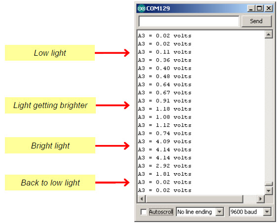
The PhototransistorVoltage sketch makes the Serial Monitor display the voltage measured at A3—one of the  Arduino’s five analog input channels that are accessible through the BOE Shield.  In the circuit you just built, a wire connects A3 to the row where the phototransistor’s emitter and resistor meet.  The voltage at this part of the circuit will change as the light level sensed by the phototransistor changes.  The Serial Monitor screencapture below shows some example voltage measurements.

  • Reconnect programming cable and battery pack power to your board.
  • Put the BOE Shield’s power switch in position 1.
  • Enter, save, and upload  the PhototransistorVoltage sketch to your Arduino. 
  • Slowly move the flashlight or lamp over the phototransistor, and watch the value of A3 in the Serial Monitor.  Brighter light should cause larger voltage values and dimmer light should cause smaller voltages.
  • If the ambient light is brighter than just fluorescent lights, and you have a bright flashlight, you may need to replace the 2 kΩ resistor with a smaller value.  Try 1 kΩ, 470 Ω, or even 220 Ω for really bright lights.
  • If the ambient light is low, and you are using a fluorescent desk lamp bulb or an LED flashlight for your bright light, you may need to change the 2 kΩ resistor to 4.7 kΩ, or even 10 kΩ.
  • Record values for ambient light (your normal room light levels), and then bright light, like when you shine a flashlight right on the phototransistor.  Make a note of them—you’ll need them for the sketch after this one.
/*
 * Robotics with the BOE Shield - PhototransistorVoltage
 * Display voltage of phototransistor circuit output connected to A3 in
 * the serial monitor.
 */

void setup()                                 // Built-in initialization block
{
  Serial.begin(9600);                        // Set data rate to 9600 bps
}

void loop()                                  // Main loop auto-repeats
{
  Serial.print("A3 = ");                     // Display "A3 = "
  Serial.print(volts(A3));                    // Display measured A3 volts
  Serial.println(" volts");                  // Display " volts" & newline
  delay(1000);                               // Delay for 1 second
}
                                             
float volts(int adPin)                       // Measures volts at adPin
{                                            // Returns floating point voltage
 return float(analogRead(adPin)) * 5.0 / 1024.0;
}    


Printer-friendly version
Activity 1: Simple Light to Voltage Sensor
Prev
Halt Under the Bright Light
Next

DISCUSSION FORUMS | PARALLAX INC. STORE

About | Terms of Use | Feedback: learn@parallax.com | Copyright©Parallax Inc. 2024

© 2026 Parallax Learn • Built with GeneratePress