Skip to content
Parallax Learn

Parallax Learn

  • Welcome
  • Tutorials
        • Tutorial Series head tag

          Tutorial Series
        • Tutorial Series

          The special, classroom-ready series pages are organized collections of tutorials for our most popular hardware and/or languages. The tutorials for each topic are conveniently accessible from a single page, shown in the order it is recommended that they be completed.
        • Robotics Series Head tag

          Robotics Series
        • Robotics Series

          • Artificial Intelligence
          • Cybersecurity: Radio Data tutorialCybersecurity
          • cyber:bot + Python
          • cyber:bot + MakeCode
          • Boe-Bot Tutorial SeriesBoe-Bot
          • Arduino Shield-Bot
          • ActivityBot with C TutorialsActivityBot + C
          • ActivityBot with BlocklyProp Tutorial SeriesActivityBot + BlocklyProp
          • Scribbler 3 Tutorial SeriesScribbler 3
        • Electronics & Programming Series Head tag

          Electronics & Programming Series
          • BS2 Board of Education Tutorial SeriesBS2 Board of Education
          • Propeller C-Language BasicsPropeller C Basics
          • FLiP Try-It Kit C Tutorial SeriesFLiP Try-It Kit + C
          • FLiP Try-It Kit BlocklyProp TutorialsFLiP Try-It Kit + BlocklyProp
          • Badge WX Tutorial SeriesBadge WX
          • Propeller BlocklyProp Basics and ProjectsPropeller BlocklyProp Basics
          • View All Tutorial Series »
        • Browse Tutorials
        • Browse Tutorials

          Individual tutorials sorted by robot or kit, and language.
        • By Robot or Kit
          • ActivityBot
          • SumoBot WX
          • Boe-Bot
          • Shield-Bot
          • cyber:bot
          • Badge WX
          • ELEV-8
          • ARLO
        • By Language
        • By Language

          • Propeller C
          • Arduino
          • BlocklyProp
          • PBASIC
          • Python
          • MakeCode
          • View All Tutorials »
  • Educators
  • Reference
  • Downloads
  • Home
  • All Courses

Robotics with the Board of Education Shield for Arduino

Curriculum

  • 9 Sections
  • 148 Lessons
  • Lifetime
Expand all sectionsCollapse all sections
  • About This Tutorial
    3
    • 2.0
      About the BOE Shield-Bot
    • 2.1
      Audience and Support
    • 2.2
      Author & Contributors
  • Chapter 1. Your Shield-Bot's Brain
    25
    • 3.1
      Chapter 1. Your Shield-Bot’s Brain
    • 3.2
      Hardware and Software Options
    • 3.3
      Shield-Bot Chassis Parts
    • 3.4
      Shield-Bot Hardware
    • 3.5
      Shield-Bot Electronics Parts
    • 3.6
      Activity 1: Download and Install the Software
    • 3.7
      Activity 2: Write a Simple “Hello!” Sketch
    • 3.8
      Codebender Hello Sketch
    • 3.9
      How the Hello Sketch Code Works
    • 3.10
      Modify the Sketch to Repeat
    • 3.11
      Hello Messages on New Lines
    • 3.12
      Open the Arduino Reference
    • 3.13
      Activity 3: Store and Retrieve Values
    • 3.14
      Global vs.Local Variables
    • 3.15
      Activity 4: Solve Math Problems
    • 3.16
      Try Floating Point Math
    • 3.17
      Activity 5: Make Decisions
    • 3.18
      More Decisions with if… else if
    • 3.19
      Activity 6: Count and Control Repetitions
    • 3.20
      How the for Loop Works
    • 3.21
      Adjust Initialization, Condition, and Increment
    • 3.22
      Activity 7: Constants and Comments
    • 3.23
      Chapter 1 Summary
    • 3.24
      Chapter 1 Challenges
    • 3.25
      Chapter 1 Solutions
  • Chapter 2. Shield, Lights, Servo Motors
    23
    • 4.0
      Chapter 2. Shield, Lights, Servo Motors
    • 4.1
      Activity 1: Board of Education Shield Setup
    • 4.2
      Activity 2: Build and Test LED Indicator Lights
    • 4.3
      Introducing the Resistor
    • 4.4
      Introducing the LED
    • 4.5
      Introducing the Prototyping Area
    • 4.6
      LED Test Circuit
    • 4.7
      How a Sketch Makes the LED Turn On and Off
    • 4.8
      Introducing the Timing Diagram
    • 4.9
      Activity 3: LED Servo Signal Monitors
    • 4.10
      How to Use the Arduino Servo Library
    • 4.11
      Activity 4: Connect Servo Motors and Batteries
    • 4.12
      Connect the Servos to the BOE Shield
    • 4.13
      Connect the Battery Pack to the BOE Shield
    • 4.14
      5-cell Pack Setup
    • 4.15
      4-cell Pack + Boe-Boost Setup
    • 4.16
      Activity 5: Centering the Servos
    • 4.17
      Activity 6: Testing the Servos
    • 4.18
      Controlling Servo Speed and Direction
    • 4.19
      How To Control Servo Run Time
    • 4.20
      Chapter 2 Summary
    • 4.21
      Chapter 2 Challenges
    • 4.22
      Chapter 2 Solutions
  • Chapter 3. Assemble and Test your BOE Shield-Bot
    22
    • 5.0
      Chapter 3. Assemble and Test your BOE Shield-Bot
    • 5.1
      Activity 1: Assembling the BOE-Shield-Bot
    • 5.2
      Mount the Topside Hardware
    • 5.3
      Remove the Servo Horns
    • 5.4
      Mount the Servos on the Chassis
    • 5.5
      Mount the Battery Pack
    • 5.6
      Mount the Wheels
    • 5.7
      Attach the BOE Shield to the Chassis
    • 5.8
      Activity 2: Re-test the Servos
    • 5.9
      Testing the Left and Right Wheels
    • 5.10
      Servo Troubleshooting
    • 5.11
      Activity 3: Start-Reset Indicator
    • 5.12
      Build the Piezospeaker Circuit
    • 5.13
      Programming the Start-Reset Indicator
    • 5.14
      Example Sketch: StartResetIndicator
    • 5.15
      Activity 4: Test Speed Control
    • 5.16
      Example Sketch: Test Servo Speed
    • 5.17
      How TestServoSpeed Works
    • 5.18
      Optional: Record Your Own Transfer Curve Data
    • 5.19
      Chapter 3 Summary
    • 5.20
      Chapter 3 Challenges
    • 5.21
      Chapter 3 Solutions
  • Chapter 4. BOE Shield-Bot Navigation
    19
    • 6.0
      Chapter 4. BOE Shield-Bot Navigation
    • 6.1
      Activity 1: Basic BOE Shield-Bot Maneuvers
    • 6.2
      How ForwardThreeSeconds Works
    • 6.3
      Moving Backward, Rotating, and Pivoting
    • 6.4
      Activity 2: Tuning the Basic Maneuvers
    • 6.5
      Tuning the Turns
    • 6.6
      Activity 3: Calculating Distances
    • 6.7
      Activity 4: Ramping Maneuvers
    • 6.8
      Activity 5: Simplify Navigation with Functions
    • 6.9
      Function Call with Parameters
    • 6.10
      Put Maneuvers Into Functions
    • 6.11
      Activity 6: Custom Maneuver Function
    • 6.12
      Activity 7: Maneuver Sequences with Arrays
    • 6.13
      Using Array Elements
    • 6.14
      Navigation with Arrays
    • 6.15
      Character Arrays and switch-case
    • 6.16
      Chapter 4 Summary
    • 6.17
      Chapter 4 Challenges
    • 6.18
      Chapter 4 Solutions
  • Chapter 5. Tactile Navigation with Whiskers
    13
    • 7.0
      Chapter 5. Tactile Navigation with Whiskers
    • 7.1
      Activity 1: Build and Test the Whiskers
    • 7.2
      How Whisker Switches Work
    • 7.3
      Testing the Whiskers
    • 7.4
      How DisplayWhiskerStates Works
    • 7.5
      Activity 2: Field-Test the Whiskers
    • 7.6
      Activity 3: Navigation with Whiskers
    • 7.7
      How RoamingWithWhiskers Works
    • 7.8
      Activity 4: Artificial Intelligence for Escaping Corners
    • 7.9
      How Escaping Corners Works
    • 7.10
      Chapter 5 Summary
    • 7.11
      Chapter 5 Challenges
    • 7.12
      Chapter 5 Solutions
  • Chapter 6. Light-Sensitive Navigation with Phototransistors
    18
    • 8.0
      Chapter 6. Light-Sensitive Navigation with Phototransistors
    • 8.1
      Introducing the Phototransistor
    • 8.2
      Activity 1: Simple Light to Voltage Sensor
    • 8.3
      Example Sketch: PhototransistorVoltage
    • 8.4
      Halt Under the Bright Light
    • 8.5
      How the Phototransistor Circuit Works
    • 8.6
      Ohm’s Law
    • 8.7
      Activity 2: Measure Light Levels Over a Larger Range
    • 8.8
      Building the Photosensitive Eyes
    • 8.9
      Test the Phototransistor Circuit
    • 8.10
      rcTime and Voltage Decay
    • 8.11
      Activity 3: Light Measurements for Roaming
    • 8.12
      Light Measurement Graphic Display
    • 8.13
      Activity 4: Test a Light-Roaming Routine
    • 8.14
      Activity 5: Shield-Bot Navigating by Light
    • 8.15
      Chapter 6 Summary
    • 8.16
      Chapter 6 Challenges
    • 8.17
      Chapter 6 Solutions
  • Chapter 7. Navigating with Infrared Headlights
    14
    • 9.0
      Chapter 7. Navigating with Infrared Headlights
    • 9.1
      Infrared Light Signals
    • 9.2
      Activity 1: Build and Test the Object Detectors
    • 9.3
      Object Detection Test Code
    • 9.4
      Activity 2: Field Testing
    • 9.5
      Sniffing for IR Interference
    • 9.6
      Activty 3: Detection Range Adjustments
    • 9.7
      Activity 4: Object Detection and Avoidance
    • 9.8
      Activity 5: High-performance IR Navigation
    • 9.9
      Activity 6: Drop-off Detector
    • 9.10
      Example Sketch: AvoidTableEdge
    • 9.11
      Chapter 7 Summary
    • 9.12
      Chapter 7 Challenges
    • 9.13
      Chapter 7 Solutions
  • Chapter 8. Robot Control with Distance Detection
    11
    • 10.0
      Chapter 8. Robot Control with Distance Detection
    • 10.1
      Activity 1: Testing the Frequency Sweep
    • 10.2
      Displaying Both Distances
    • 10.3
      Activity 2: BOE Shield-Bot Shadow Vehicle
    • 10.4
      A Look Inside Proportional Control
    • 10.5
      Example Sketch: FollowingShieldBot
    • 10.6
      Follow the Leader
    • 10.7
      Activity 3: What’s Next?
    • 10.8
      Chapter 8 Summary
    • 10.9
      Chapter 8 Challenges
    • 10.10
      Chapter 8 Solutions

Introducing the LED

Introducing the LED

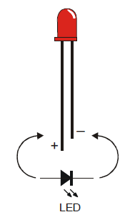
A diode is a one-way electric current valve, and a light-emitting diode (LED) emits light when current passes through it.  Since an LED is a one-way current valve, you have to make sure to connect it the right way for it to work as intended. 

An LED has two terminals: the anode and the cathode. The anode lead is labeled with the plus-sign (+) in the part drawing, and it is the wide part of the triangle in the schematic symbol.  The cathode lead is the pin labeled with a minus-sign (-), and it is the line across the point of the triangle in the schematic symbol.

When you build an LED circuit, you will have to make sure the anode and cathode leads are connected to the circuit properly. You can tell them apart by the shape of the LED’s plastic case.  Look closely at the case—it’s mostly round, but there is a small flat spot right near one of the leads, and that tells you it’s the cathode. Also note that the LED’s leads are different lengths.  Usually, the shorter lead is connected to the cathode.

Always check the LED’s plastic case.
Usually, the longer lead is connected to the LED’s anode, and the shorter lead is connected to its cathode. But sometimes the leads have been clipped to the same length, or a manufacturer does not follow this convention.  So, it’s best to always look for the flat spot on the case.  If you plug an LED in backwards, it will not hurt it, but it won’t emit light until you plug it in the right way.


Printer-friendly version
Introducing the Resistor
Prev
Introducing the Prototyping Area
Next

DISCUSSION FORUMS | PARALLAX INC. STORE

About | Terms of Use | Feedback: learn@parallax.com | Copyright©Parallax Inc. 2024

© 2026 Parallax Learn • Built with GeneratePress