How the micro:bit Ohmmeter Works
In the diagram, R1 is the resistance of the part you are measuring. Vo is the voltage that results between R1 and the 2000 Ω resistor. The multimeter module measures the voltage between the two resistors with P1. Then, it uses the R1 = … equation near the bottom of the diagram to calculate the value of R1. For example, if P1 measures 2.97 V, the result of the equation will be 220 Ω. If P1 measures 2.2 V, the result of the equation will be 1000 Ω.
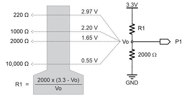
- Try substituting 2.2 for Vo in the R1 = … equation. Was the result 1000?
When two resistors are connected end-to-end, they are connected in series.
When voltages like 3.3 V and GND are applied to the ends of two resistors in series, it is called a voltage divider. The name came from the fact that the voltage at Vo is “divided” between the two resistors. In the Voltage Dividers lesson, you will experiment more with this and optionally derive the equation for calculating R1.
Modern multimeters expand the circuit and script to automatically measure anything from a fraction of an ohm to millions of ohms.
Try This - Measure a Different Resistor
Let’s measure a different resistor. Keep in mind that accuracy is best in the 100 Ω to 10,000 Ω range. Outside that range, measurement errors increase, and you’d need a different resistor and some script adjustments.
- Use the animation and the instructions below it to measure the 1000 Ω resistor with your micro:bit ohmmeter.
- Optionally, view the full-size measure-resistance-1k.mp4 clip to play and pause it between steps.
- Reconnect the resistor to the LED circuit, the light should come back on.
- Connect the 1000 Ω resistor in row 21 between the two alligator clip probes.