How It Works
- Watch the animation as it repeats, and answer each of the questions below about the differences between pressed and not pressed. Optionally, view higher res version with pause control: pb-top-button-digital-read.mp4.
- At the bottom, what value does pin6.read_digital() return that gets stored in the state variable?
- Pressed __________, not pressed __________.
- What is the voltage at the P6 pin?
- Pressed __________, not pressed __________.
- In the schematic, is the 3.3 V supply connected to (or insulated from) the rest of the circuit.
- Pressed __________, not pressed __________.
- Which supply voltage do you think the right terminal strip’s (a-e, 25) row is connected to?
- Pressed __________, not pressed __________.
- In the micro:bit, what value does it switch to internally if its pin P6 is set to input? (Hint: The answer is shown near the USB connection.)
- Pressed __________, not pressed __________.
(Answers are in the Teacher's Guide.))
Inside the pushbutton_test Script
This script is short, but it contains some important instructions that are unique to the micro:bit module hardware.
To begin, the state = 0 statement just creates a variable named state that will be used inside the while True loop.
state = 0
The micro:bit module’s P6 pin is part of the module's 5x5 LED display grid. The display.off() call prevents the LED circuits built into the micro:bit from interfering with the pushbutton circuit you just built on the breadboard.
display.off()
The 10 kΩ resistor connected to the pushbutton is called a pull-down resistor. More about that later! P6 also has an internal pull-down resistor enabled by default, and this statement disables it since a 10 kΩ pulldown resistor has been added to the circuit on your breadboard. Many microcontrollers used in
pin6.set_pull(pin6.NO_PULL)
Inside the main loop, when the pushbutton is pressed, the circuit applies 3.3 V to the P6 pin. The pin6.read_digital() call returns 1 when it detects 3.3 V. If the button is released, the circuit applies 0 V to the pin, and pin6.read_digital() returns 0 instead. In state = pin6.read_digital(), the state variable stores that 1 or 0 result.
while True:
    state = pin6.read_digital()
Next, the print statement displays "state = " followed by the 1 or 0 that just was stored in the state variable.
print("state = ", state)
Last in the loop, the sleep(250) call just slows down the display to make it easier to observe the transitions from 0 to 1 and 1 to 0.
sleep(250)
Try This
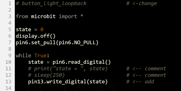
The binary (1 or 0) value returned by the pin6.read_digital() method can be used as the argument to turn the LED light on and off in pin13.write_digital(state). When state is 1 because the button is pressed, pin13.write_digital(state) becomes pin13.write_digital(1). This sets the P13 LED light to on. When the state variable is 0 because the button is not pressed, pin13.write_digital(state) becomes pin13.write_digital(0). This sets the LED light to off.
- Set the project name field to button_light_loopback.
- Update your script to match the one below, then click Save.
- Click Send to micro:bit.
- Verify that the green light connected to P13 stays off when the button is not pressed.
- Press and hold the button. Verify that the P13 light stays on while the button is held down.