Some motors can draw more current than a USB port is designed to supply to peripheral devices. So, for motor control, we typically use a battery pack to supply the motor current. In this activity, you will:
- Load new AAA batteries into the battery holder.
- Connect it to the Edge I/O Adapter compatible with BBC micro:bit.
- Test the voltage to make sure the batteries still have enough charge.
Parts
(1) Standard servo - 3 V
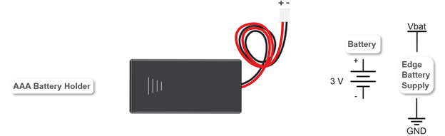
(1) AAA cell battery pack
(2) New alkaline 1.5 V AAA batteries
Circuit
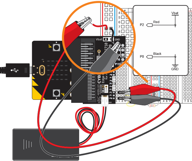
When a battery pack is plugged into the Edge I/O adapter, the voltage/current it can supply is available through the left bus strip’s (+) and (-) columns.
- Connect the red P2 probe to the left bus strips (+) rail -in one of the sockets adjacent to the red, vertical line.
- Connect the black P0 probe to the left bus strips (-) rail -in one of the sockets adjacent to the blue, vertical line.
- Load 2 AAA batteries into the micro:bit battery pack and connect it to the JST connector on the Edge I/O Adapter for micro:bit as shown in the circuit drawing.
Make sure to remove the batteries from the battery pack when it’s not in use. Otherwise, the circuit will drain the batteries.
JST is an abbreviation for Japan Solderless Terminal, a standard established by JST Mfg. Co. Small, white plastic connectors like the ones you see on the micro:bit and the Edge Adapter are commonly used inside products and appliances. We don’t normally see them since they are on printed circuit boards (PCBs) that are built into the product. The black fiberglass micro:bit and Edge I/O Adapter boards are examples of PCBs.