In these activities, you will write scripts to control the servo motor directly. In addition, you will also incorporate the pushbutton circuits from earlier activities for servo control and the LED circuits as indicators.
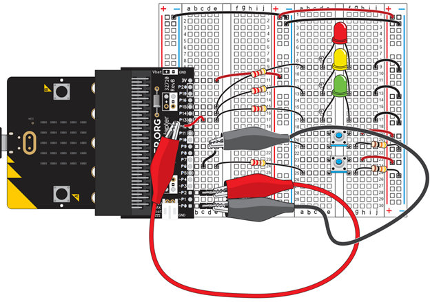
- If you already have the setup from Measure Pushbutton LED Control with an Oscilloscope (repeated below), then skip to the next section: Battery Pack: Load, Connect, Test.
- If you do not already have it built up:
- Use the schematic, wiring diagram, and Parts List from Earlier Activities below to get your setup to the starting point for this tutorial. Then use the following two tests to check your setup.
- Follow the instructions in Script and Tests from the Blink Sequencing activity in LED Lights.
- Follow the instructions in Script and Tests from the Second Pushbutton activity in Sense Pushbutton Presses.
Parts Lists from Earlier Activities
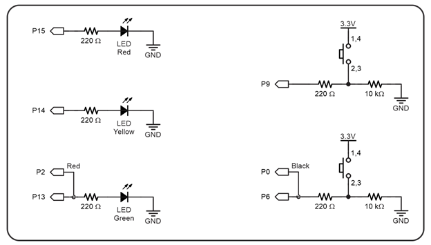
Green, yellow and red LED circuits connected to P13, P14, and P15 from Blink Sequencing:
- (1) LED - Red
- (1) LED - Yellow
- (1) LED - Green
- (3) Resistors - 220 Ω (red-red-brown-gold)
- (3) Jumper wires - black
Pushbutton circuit connected to P6 from Build & Test a Pushbutton and pushbutton circuit connected to P9 with parts from Inside the Pushbutton plus parts and circuit from Second Pushbutton.
- (2) Resistors - 220 Ω (red-red-brown-gold)
- (2) Resistors - 10 kΩ (brown-black-orange-gold)
- (2) Jumper wires - red
- (2) Pushbuttons
Alligator clip probes from First Electrical Connections with a Breadboard and recently used in Measure Pushbutton LED Control with an Oscilloscope:
- (1) Alligator clip probe - red
- (1) Jumper wire - red
- (1) Alligator clip probe - red
- (1) Jumper wire - red
Always Leave on Your Board:
Jumper wires that connect the 3V to the (+) bus strips and GND to the (-) bus strips from Set Power for Circuits:
- (2) Jumper wires - red
- (2) Jumper wires - black
3-pin headers from First Electrical Connections with a Breadboard that connect the alligator clip probes to P2 and P0:
- (2) 3-pin headers
If you completed Measure Resistance, leave these Ohmmeter Circuit parts connected to your board too:
- (2) 3-pin headers
- (1) Resistor - 2 kΩ (red-black-red-gold)
- (1) Jumper wire - yellow