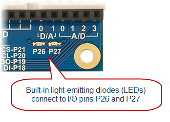
Your Activity Board WX version has two built-in lights, near the bottom-right corner of the board. These tiny light-emitting diodes (LEDs) are already electrically connected to I/O pins P26 and P27. These LEDs are helpful when developing applications that use sensors. The idea is to write your program so that if a sensor is activated, an LED lights up to give you, the roboticist, a quick visual cue that the sensor is actually detecting something.
We'll experiment with the "O" (output) feature of an I/O pin by programming the Propeller to use an I/O pin to turn a light on and off.
Circuit
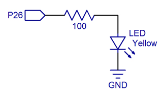
Our light circuit is already built into the Propeller Activity Board WX. Here is what the schematic looks like for this circuit:
- The Propeller I/O pin, labeled P26, is like an arrow pointing away from the label. This notes that an electrical signal will be going out of the I/O pin into the circuit.
- The zig-zag line represents a 100 ohm resistor. It resists the flow of electrical current to the LED.
- The triangle with the line under it and arrows represets the LED, which is a Light Emitting Diode.
- The GND symbol is for ground, completing the circuit.
See the Schematic Symbols reference.
Test Code
Let’s try running an example program that blinks the LED light connected to P26.
- Click SimpleIDE’s Open Project button.
- Navigate to ...Documents\SimpleIDE\Learn\Examples\Circuits.
- Open Blink Light.side.
- Set the power switch to position 1 (if applicable for your board).
- Click the Load RAM & Run button.
- Verify that it makes the P26 light blink.
How it Works
The function call high(26) sets the Propeller chip's P26 I/O pin to output-high, which connects the pin to its 3.3 V supply. The pin applies 3.3 V of electrical pressure to the LED circuit, causing electric current to pass through it and the light to turn on. After that, pause(100) makes the program do nothing for 100 ms, which keeps the light on for 1/10 of a second.
Next, low(26) sets P26 to output-low, which connects the pin to its 0 V ground supply voltage instead. This takes away the electrical pressure, so the current stops flowing through the circuit and the light turns off. Another pause(100) makes the light stay off for 1/10 of a second.
Those four commands are in a code block in a while(1) loop, which repeats endlessly, so the light keeps blinking.
/*
  Blink Light.c

  Blink light circuit connected to P26.
*/

#include "simpletools.h"                      // Include simpletools

int main()                                    // main function
{
  while(1)                                    // Endless loop
  {
    high(26);                                 // Set P26 I/O pin high
    pause(100);                               // Wait 1/10 second
    low(26);                                  // Set P26 I/O pin low
    pause(100);                               // Wait another 1/10 second
  }
}
Did You Know?
The simpletools library has lots of useful functions for controlling and monitoring circuits; high, low, and pause are just three examples. Click the SimpleIDE Help menu and choose Simple Library Reference to see a link to the simpletools library's functions.
Try This
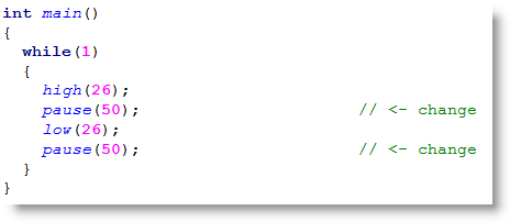
You can make the light blink faster by reducing the pause function’s parameter value. For example, to blink the light twice as fast, just reduce the pauses to half as long.
- Click the Save Project As button, and save a copy of your project named Blink Light Faster.
- Modify the main function as shown below.
- Run the program and verify the output.
Your Turn
Try controlling the P27 light along with the P26 light.
- Modify your program so that it turns both lights on and off at about the same time.
- Modify your program so that whenever one light is on, the other is off.