You can do more than just blink the LEDs attached to the ELEV-8 Flight Controller - you can connect the flight controller to an external LED, or even another development board like the Activity Board or an Arduino!
Although this part of the tutorial is optional, it is helpful to see how the flight controller can be programmed to control an external accessory such as a data-logging sensor.
Connect an external LED
Instead of turning on an LED on the Flight Controller itself, let's try turning on an external LED - this will demonstrate that the pins on the flight controller can be connected to external devices.
- If you have not completed the previous pages in this tutorial, you must follow the instructions on those pages first.
- Using SimpleIDE, open the flight controller firmware.
- Verify that you care editing elev8-main.cpp file.
- Find the following code that you added on the last page (near line 200):
// Set up the 3 pins attached to the LEDs as outputs
FCsetAsOutput(21);
FCsetAsOutput(22);
FCsetAsOutput(23);
FCsetAsInput(1);
FCsetAsInput(2);
FCsetAsInput(3);
- Delete those lines of code and add:
FCsetAsOutout( PIN_MOTOR_AUX1 );
- Next, find the code that you added after the line UpdateFlightLEDColor(); (near line 660).
- Delete the changes you made in the previous page.
- Add the following code:
  if( Radio.Gear < -512  )  // Check the gear(mode) switch position
  {
    FC_low( PIN_MOTOR_AUX1 );      // Turn the external LED of
  } else {
    FC_high( PIN_MOTOR_AUX1 );     // Turn the external LED on
  }
- Save your project.
DO NOT CONNECT YOUR ELEV-8's Battery. Make sure the propellers have been removed from your ELEV-8 quadcopter before continuing.
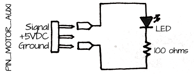
- Using jumper wires or another 3-pin cable with a a long 3-pin header, connect the signal and ground pins from the PIN_MOTOR_AUX1 pin to the breadboard:
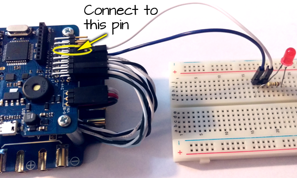
- Plug your ELEV-8 v3 Flight Controller into your computer and select the corresponding port from the drop-down menu.
- Click the Upload to EEPROM button.
- Once the program has loaded, turn on your transmitter.
- When you flip the gear switch, the LED will blink on and off.
Build a cable to power another development board from the Power Distribution Board
If you wish to connect another development board such as an Activity Board or an Arduino to your ELEV-8 v3, you will need a way to power that board.
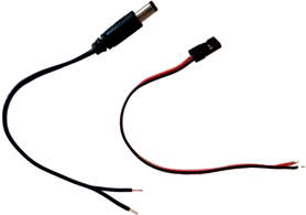
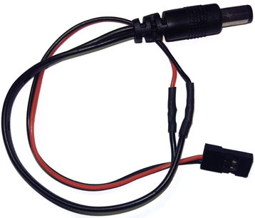
- Gather your materials.
- Cut one end off of the 3-pin cable and cut off or remove the white wire entirely.
- Strip the ends of the wires on both the 3-pin cable and the barrel plug cable:
- If you plan to heat-shrink the connections, slide pieces of heat shrink over the ends of the 3-pin cable.
- Using a soldering iron, connect the wire with the white stripe on the barrel plug to the red wire on the 3-pin cable:
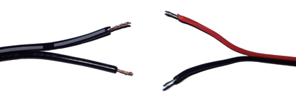
- Again using a soldering iron, connect the solid black wires from the barrel plug and the 3-pin cable together.
- Apply to heat to the heat-shrink or use electrical tape to prevent the soldered connections from touching and shorting:
- Connect the 3-pin end to the Power Distribution Board on the ELEV-8 v3.
- (Optional) Using 4-40 hardware, zip-ties, or adhesive, mount your development board to your ELEV-8 v3.
- Plug the barrel plug into your development board.
Connecting an Activity Board to the Flight Controller
Although this example is specific to an Activity Board, the same concepts can be used to connect and Arduino or even a BASIC Stamp development board.
In this example of two-way communication, when the gear (mode) switch is flipped on, the Flight Controller sets one of its pins high. This pin, which is connected to an Activity Board, tells the Activity Board to begin its program. The Activity Board then turns on 3 LEDs in 3 seconds. Then, the Activity Board sets one of its pins, which is connected back to the Flight Controller, high. When the Flight Controller detects that that pin is high, it turns on one of its on-board LEDs.
This application is especially useful because the Activity Board has an SD card slot and is able to do data-logging with any sensor that you are able to attach to it. Click here for a tutorial on using the Activity Board to record data to an SD card.
- If you have not completed the previous pages in this tutorial, you must follow the instructions on those pages first.
- Using SimpleIDE, open the flight controller firmware.
- Verify that you care editing elev8-main.cpp file.
- Delete the code that you added on the last activity (near line 200):
// Set up the 3 pins attached to the LEDs as outputs
FCsetAsOutput(23);
FCsetAsOutput(PIN_MOTOR_AUX1);
FCsetAsInput(PIN_MOTOR_AUX2);
- Next, find the code that you added after the line UpdateFlightLEDColor(); (near line 660).
- Delete the changes you made in the previous activity.
- Add the following code:
  if( Radio.Gear < -512  )             // Check the gear(mode) switch position
  {
    FC_low( PIN_MOTOR_AUX1 );          // Turn off the Activity Board trigger
  } else {
    FC_high( PIN_MOTOR_AUX1 );         // Turn on the Activity Board trigger
  }

  if( FC_input(PIN_MOTOR_AUX2) == 1 )  // Check if the Activity Board is sending a signal
  {
    FC_low(23);                        // Turn on the on-board LED
  } else {
    FC_high(23);                       // Turn off the on-board LED
  }
- Save your project.
DO NOT CONNECT YOUR ELEV-8's Battery. Make sure the propellers have been removed from your ELEV-8 quadcopter before continuing.
- Plug your ELEV-8 v3 Flight Controller into your computer and select the corresponding port from the drop-down menu.
- Click the Upload to EEPROM button.
- In SimpleIDE, click "File > New Project" and open a new C (not C++) project.
- Delete the blank template and type in the following code:
#include "simpletools.h"                      // Include simple tools

int main()                                    // Main function
{
  // Add startup code here.
  while(1)
  {
    low(26);                 // make sure all LEDs
    low(27);                 // and the Flight Controller
    low(3);                  // trigger are off
    low(10);

    if(input(11) == 1)       // Did the flight controller send
    {                        // a high signal?
      high(26);              // Turn on the first LED
      pause(1000);           // Wait 1 second
      high(27);              // Turn on the second LED
      pause(1000);           // Wait 1 second
      high(3);               // Turn on the third LED
      pause(1000);           // Wait 1 second
      high(10);              // Send a signal to the Flight Controller

      while(input(11) == 1); // Wait until the Flight Controller stops
    }                        // sending a high signal
  }
}
- Connect the Activity Board to your computer.
- Make sure the correct port is selected, and click the to EEPROM button.
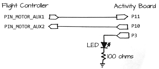
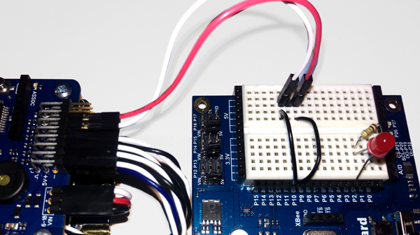
- Once the program has loaded, use jumper wires to connect your Activity Board to your Flight Controller as shown:
- Connect the power cable you built earlier from the Power Distribution Board to the Activity Board.
- Turn on your transmitter.
- Connect the battery.
- Flip the gear (mode) switch on your transmitter to trigger the code and observe the two boards communicating with each other.