Run The Program
Once you complete the build and load the code, go ahead and power up the unit. Observe its response. Make sure you're able to bring the arm all the way in, and all the way out by moving the joystick right then left. If you are unable to achieve full motion, adjust the position of the arm by removing the center screw holding each servo horn and placing it in different positions on the servo spline until you achieve the maximum range of motion.
Now you can start experimenting with your robotic servo drawing arm and bring out your inner Picasso!
How Does it Work?
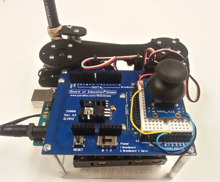
The joystick in this application is essentially two potentiometers. One for the x axis and one for the y axis. As a you push or pull the joystick in any direction you are essentially changing the resistance value of one or both potentiometers.
When resistance changes the joystick outputs a voltage from each of its axis and feeds the variable voltages into two analog to digital converter pins(A0 ,A1) on the Arduino shield and Arduino Uno.
The Arduino uses it's built in analog to digital converter(ADC) to convert analog data to digital data. This conversion is called quantization. Once the data is converted to digital, the code can then use it to determine what position each servo should be in to achieve a desired motion and/or position. See the code comments for explanation of the code.
Did You Know?
This project touches on a topic used extensively in the manufacturing industry called Inverse Kinematics.
Inverse Kinematics is a mathematical technique used to plan the movement of robotic joints in order to achieve a specific motion and/or position. Check out Wikipedia to learn more about it.