This is an easy application to build, however it is assumed that you already have laser-cut the three pieces of plastic that make up the body of the arm using the file provided, or have suitable replacement/stand in parts. For those without access to a laser cutter, you can use the Parts Drawings download to create your own parts using a method of your choice:
Build It
- Build your retrofit kit as per the PDF instructions for the kit (http://www.parallax.com/sites/default/files/downloads/35000-BOE-Shield-Documentation-v1.2.pdf)
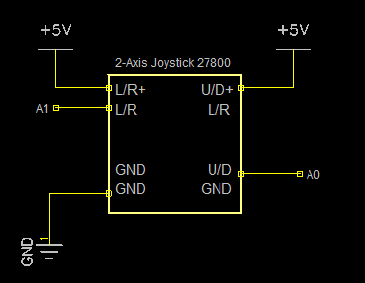
- Then build the joystick circuit using the following schematic image:
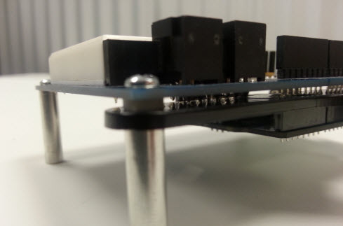
- In order to attach the base of the robotic arm to the shield, you will need to remove the front mounting screws. Line up the holes on the base with the mounting holes on the shield. Insert a plastic standoff in between the shield and the base of the robotic arm. This will ensure that the base does not touch any solder joints on the bottom side of the shield.
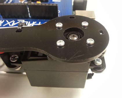
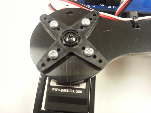
- Install a Standard Servo onto the shoulder joint of the robotic arm using (4) #4-40 3/8 inch screws and (4) #4-40 nuts. Make sure to include the servo horn. Using (4) #2-56 1/4 inch screws and nuts mount the forearm on top of the servo as shown in the picture below.
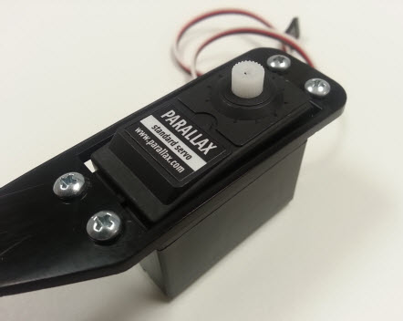
- Mount a Standard Servo onto the forearm using (4) #4-40 3/8 inch screws and nuts, and then mount them onto the upper arm (the arm attached to base unit) using (4) #2-56 1/4 inch screws and nuts as shown in the following pictures.
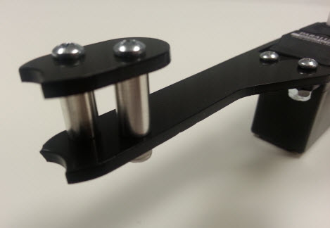
- Mount the pin holder to the tip of the forearm using (2) #4-40 7/8 inch screws, (2) #4-40 nuts and (2) standoffs. The standoff sizes can be of your choosing.
- Insert the servo cable belonging to the servo that mounts to the base into servo header P13 and the other servo cable into servo header P12.
- Connect the batteries and load the code.