Jump to navigation
Install the QTI Line Sensors
Parts:
- (1) SumoBot, built up at least through the end of the Add Cables for Front QTI Sensors page
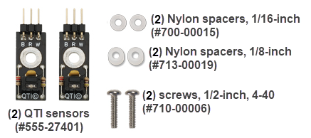
- (2) QTI line sensors
- (2) #4-40 1/2" long pan-head machine screws
- (2) 1/8" Nylon spacer
- (2) 1/16" Nylon spacer
Procedure
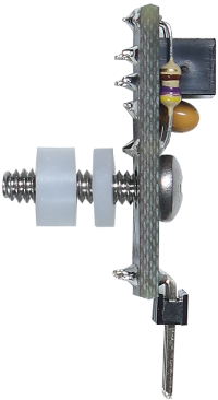
- Position the parts on each screw in this order:
- QTI with parts facing the same direction as the screw’s head
- 1/16” nylon washer
- 1/8" nylon washer.
- Connect each screw (with its QTI and washers) to a front standoff (by the plow).
- Make sure the pins of each QTI point inward -toward the slot where you just inserted the cables.
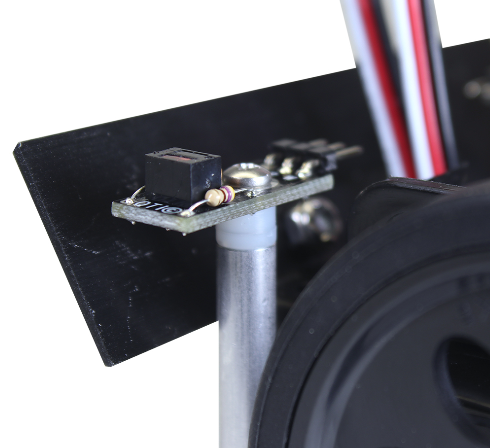
- Connect the cables you fed through the chassis to each QTI.
- Make sure that each cable’s:
- White wire is connected to the QTI’s W pin
- Red wire is connected to the QTI’s R pin
- Black wire is connected to the QTI’s B pin
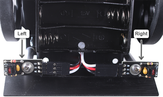
- Set the SumoBot face down on the table with its underside facing toward you, and identify the left and right QTIs.
- Follow the cable from the left QTI to its other end, and mark it L with masking tape.
- Repeat for the right cable.
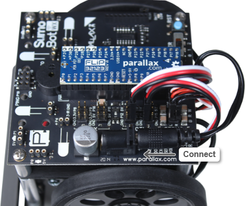
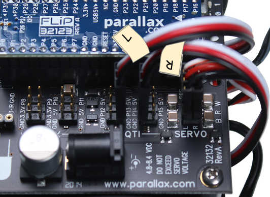
- Connect the QTI marked L to the P13 header and the QTI marked R to the P14 header.
- Make sure each cable’s:
- Black wire is connect to the pin labeled GND
- Red wire is connected to the pin with a label that begins with P (like P13 and P14).
- White wire is connected to the pin labeled 5V.
- Remove the L and R labels from the QTI cables.
- Put the batteries back into the battery holder.
- Connect the battery power plug to the barrel jack.