For best results, always test navigation and sensors separately before combining them in a robot app. Earlier, you built test programs that made the SumoBot perform a variety of maneuvers, so navigation testing is already done. Here, you will build a program that tests the values the QTI sensors measure and verify that they can detect the difference between the black and white sumo ring surfaces.
Program
This first test will verify that your SumoBot robot’s QTIs return measurements that fall in the right ranges for indicating that they are over black or white surfaces.
- Watch this animation for tips on how to build the QTIs Test Values program.
- In BlocklyProp Solo:
- Create a New Project.
- Name it QTIs Test Front Values.
- Set the Board Type of Propeller FLiP or Project Board.
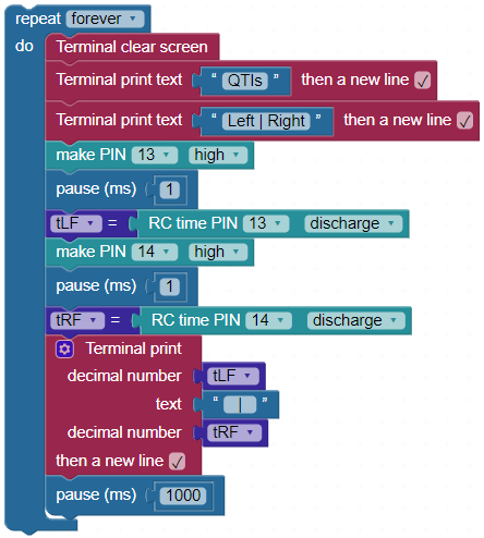
- Build you program so that it matches this image.
Tests
- While the SumoBot is still connected to your computer with USB, set the SumoBot on the sumo ring near the edge.
- Click the Load & Run (Save code to EEPROM) button to load the program into your SumoBot.
- Monitor the terminal as you place the SumoBot’s QTIs over the black and white surfaces.
- Verify that the measurement for each QTI is below 230 when you place it over the white edge of the sumo ring and above 230 when it’s over the black surface.
- Verify that the cables are not swapped:
- When you move the left QTI from black to white, the left number in the terminal should drop from above 230 to below 230.
- Repeat for the right QTI and right terminal measurement.
- If the right QTI affects the left measurement, the QTI cables might be swapped.
Tuning
It’s important to have a safety margin above and below that 230 threshold to identify black and white surfaces. For example, it would be best to ensure that white detection measurements are below 115 and black detections are above 460.
The height of the QTI’s light sensor surface above the sumo ring can have a big effect on the values. To adjust the QTI height, you can either adjust the plow height or add/remove nylon washers between the QTI and the standoff (or both).
The optimal range of distances above the sumo ring’s surface is between 1/20 and 1/10 inch (1.25 to 2.5 mm). So, it’s best to shoot for 1/16 of an inch (1.6 mm). Even if it’s up at ⅛ inch (3.175 mm), it should still work fine. Distances below 1/30 or above 3/16 of an inch (0.85 to 4.8 mm) start to approach those safety margin values or 115 for white and 460 for black).
The QRD1114 sensor’s datasheet actually says that the peak response is between 20 and 30 mils (thousandths of an inch). It’s not a good idea to mount it that close to the surface of the sumo ring because its sensitivity drops abruptly below 20 mils, but it declines gradually over 30 mils. Since the SumoBot could end up being pushed downward during a match, it’s better to have it riding higher above the surface than the datasheet specifies to make sure no incorrect measurements are reported. These factors and some additional testing all came into consideration when deciding on a 1/16 inch recommendation.
How It Works
The QTI sensor takes a certain amount of time to respond depending on how reflective the surface is. (Remember, the QTI has to be facing the surface at about 1/16 of an inch away.) The QTI responds quickly over highly reflective white surfaces and slowly over less reflective dark surfaces. Even though the measurements are actually response time values, those values indicate how reflective the surface is.
To start a measurement, the QTI needs to be “primed” with a high signal. It’s the same kind of signal you will use to turn on an LED light in an upcoming activity, and it charges the QTI so that it can send a high signal. After the Propeller FLiP stops sending a high signal, it measures the amount of time the QTI continues to send that high signal back to the Propeller FLiP. That time indicates how reflective the surface is.
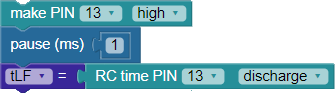
The make PIN 13 high block sends the high signal, and the pause (ms) 1 keeps that signal high for 1 millisecond, which is 1/1000 of a second. After that, the QTI is charged and ready to send the high signal back for a time that indicates reflectiveness of the surface. Next, the RC time PIN 13 discharge block makes the Propeller FLiP stop charging the QTI, and then measures how long the QTI continues to send that high signal back to the pin. It stores that microsecond (millionths of a second) time measurement in a variable named tLF. tLF is an abbreviation for time-left-front.
The same process is repeated for tRF and the QTI connected to P14.