In this activity, you will connect red light emitting diodes (LEDs) to the P5 and P6 sockets, and use them as visual indicators for sumo ring edge detection. In the next chapter, they will be removed and replaced with infrared LEDs as part of the infrared opponent detection system.
Parts
- (2) LEDs - red
Circuit
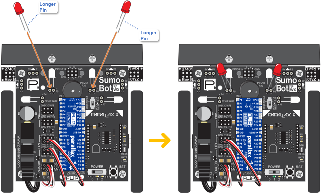
- Set the POWER switch to 0.
- Connect the LEDs as shown in the diagram. Make sure each LED’s longer pin goes into the socket next to the P5 (or P6) label.
- Set the POWER switch to 1.
Program
- Watch this animation for tips on how to modify Link QTIs Test Front BW Detect.svg to make the LED indicator lights turn on if they are above the white sumo ring border.

- Rename QTIs Test Front BW Detect.svg to QTIs Front LED Indicators by changing the name field in the upper-right.
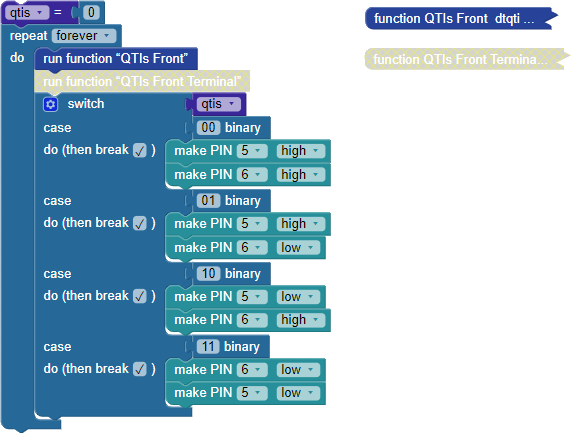
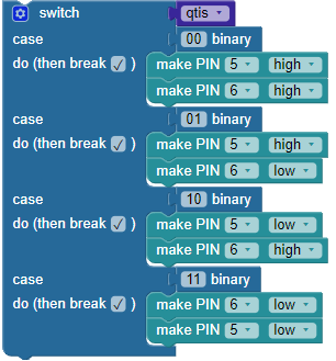
- Modify the program so that it matches this image (below).
- Click the Load & Run (Save code to EEPROM) button to load the program into your SumoBot.
Tests
- Place each QTI over black and white, and verify that the LED on the same side as the QTI turns on when the QTI is over the white border and off when it’s over black.
How It Works
A switch...case block “switches” to different cases depending on the value in the block attached to switch. When a value attached to a case input matches the switch input, the blocks in the do (then break ✓) input are executed. If the (then break ✓) box is checked, the switch...case block does not check for any more cases after the first match.
In this switch...case block, if the qtis variable stores binary 00, it turns both LEDs on with the make PIN 5 high and make PIN 6 high blocks. After that, (then break ✓) causes it to skip all the other cases. In other words, the switch...case block only runs blocks for one case and ignores all the others. The next time through the repeat loop, the qtis variable might instead store binary 01. This time, the second case of 01 binary matches the qtis variable at the switch input. So, it runs the pair of blocks for that case: make PIN 5 high and make PIN 6 low. The result for each of these cases is that LEDs turn on to indicate that a given QTI is over a white surface, or off for a black surface.
For more info on the switch...case block, look it up in the Propeller BlocklyProp Reference control page.