- Make a base any size you want that is big enough to hold the board and battery pack.
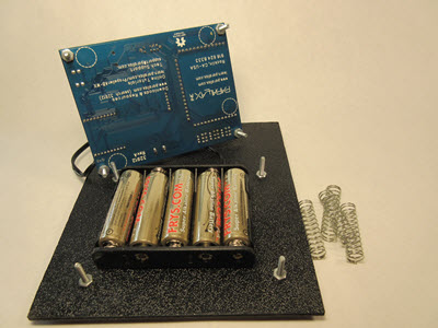
- Using the Propeller Activity Board WX for size reference, drill holes to match holes in board’s corners and insert screws from the underside of the base and secure with a nut.
- Put the other 4/40 screws in the corners of the Activity Board and secure with a nut also.
See picture below. The nuts should be positioned on the underside of the Activity Board, and on the top side of the base.
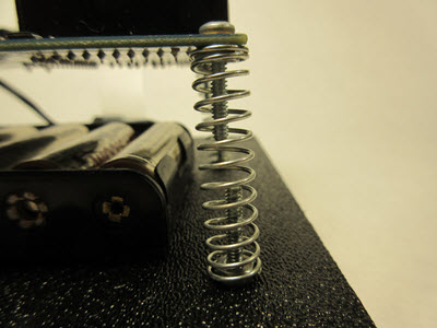
I used 1.5 inch-long by 5/8 inch-wide springs for the seismometer mounting. You want the springs to move freely so they should be long enough to keep screws from touching each other. This gives a very responsive base for the movement of whatever you set your seismometer on. I refer to the springs as “force amplifiers”. It is sensitive enough to drive you a little crazy if you put it on your desk! The width of the springs is to keep them in place by fitting snugly around the nuts.
Wiring it Up
- Follow the wiring diagrams below closely, along with the sensor placement and schematics.
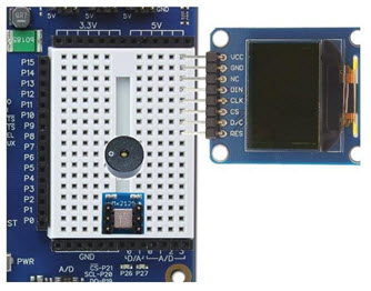
There are tutorials on these sensors on the Parallax Learn website using several languages to program them with, like Prop C, Spin, and Blocklyprop. We will be using Blocklyprop for this project because of its ease of use. Below on the left is a picture of the breadboard wiring without the sensors, and on the right is the sensor placement. You might want to place the piezospeaker and accelerometer before beginning your wiring, to make it easier. The OLED can be added after the wiring is complete.
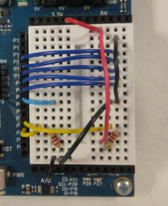
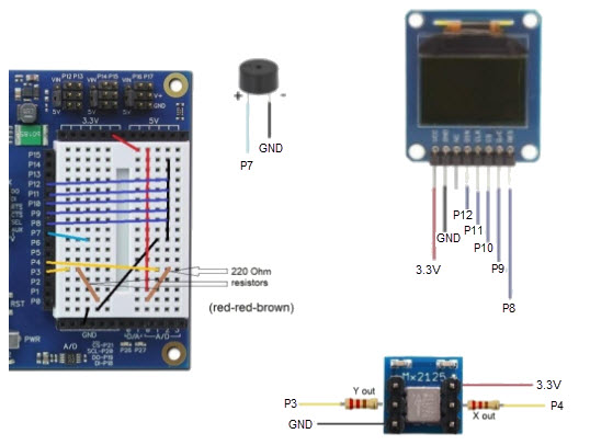
Below is a graphic representation of the wiring diagram without sensors installed, plus the schematics for each of the 3 sensors we're using in this project. The brown lines are the 220-ohm resistors pictured above, and the line colors match the colors on the sensor schematics. Make sure your project agrees with these pinouts.
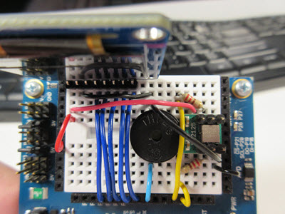
This is an image of the board fully wired, with sensors installed:
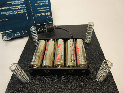
- Once the board is set up, secure the battery pack to the base, in the middle of the springs.
- Place the Activity Board WX on top of the springs so the screws secure it into the springs, and connect the barrel jack from the battery pack.