Connections differ depending on the Propeller board you choose to work with. The first set of instructions are for the Activity Board or Activity Board WX. The second set of instructions are for the Propeller FLiP on a breadboard.
Building the Circuit (Propeller Activity Board/Activity Board WX)
- Modify one end of the 3 pin cable:
- Use a tool with a fine point to carefully lift each of the tabs on the connector:
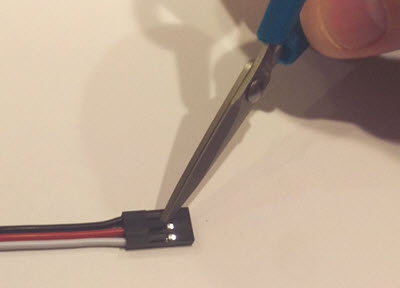
- Pull out the wires
- Arrange the wires so they are ordered RED-WHITE-BLACK and re-insert them into the connector end:

- Make sure the wires make the following connections when plugged into the coin acceptor:
- RED -> DC12V
- WHITE -> COIN
- BLACK -> GND
- Use a tool with a fine point to carefully lift each of the tabs on the connector:
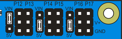
- Make sure the P12-13 shunt jumper is moved from the 5V to the VIN position:
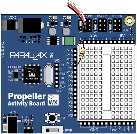
- Connect the other (unmodified) end of the 3-pin cable to the P12 header.
- Connect a 10 kOhm resistor between P12 and 3.3V.
Building the Circuit (Propeller FLiP)
- Modify one end of the 3 pin cable :
- Use a tool with a fine point to carefully lift each of the tabs on the connector:
- Pull out the wires.
- Arrange the wires so they are ordered RED-WHITE-BLACK.
- Make sure the wires make the following connections when plugged into the coin acceptor:
- RED -> DC12V
- WHITE -> COIN
- BLACK -> GND
- Use a tool with a fine point to carefully lift each of the tabs on the connector:
- Follow the diagram below to make the connections on the breadboard:
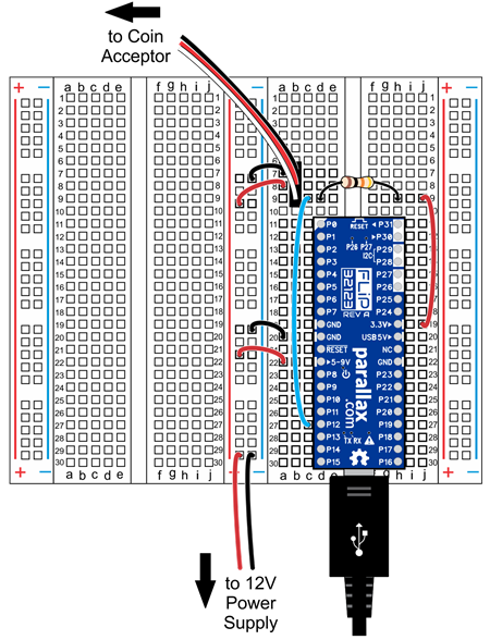
REMEMBER: The 12V supply can be connected to the (→5-9VIN pin) on the FLiP - however be aware that because the input voltage is above 9 volts, if the FLiP module’s power connections are shorted, the FLiP will get VERY HOT.