What does I2C Stand For?
The term I2C comes from the name Inter-Integrated Circuit, which would be abbreviated IIC. If those three letters were variables in an equation multiplied together, the two I terms would be I x I or I2. So, that’s where I2C comes from. It’s often pronounced I-squared-C, though I-two-C is also understood.
How Do the Propeller and Simple Libraries use EEPROM?
The Load EEPROM button copies the example Propeller program to your board's EEPROM, filling addresses 0 to 32767. So, 32768 is the first available memory address for data storage. Some Simple Libraries keep calibration data in the EEPROM. By convention, these libraries use the highest available EEPROM addresses, so if your application is logging data, it’s best to start from 32768 and allow data to accumulate upward to higher addresses.
Libraries that use EEPROM this way list the memory locations they use in their documentation. For an example, open …\Documents\SimpleIDE\Learn\Simple Libraries\Convert\libabvolts\Documentation abvolts Library.html, scroll to the Detailed Description heading, and check the EEPROM Usage info. You might also notice these addresses in the Macros section.
What Do I2C Signals Look like?
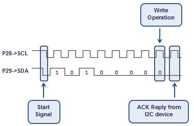
A typical I2C packet has a first byte that begins with the microcontroller master (the Propeller in this case) sending a start condition signal that takes the SDA line low, while the SCL line is high. After that, the Propeller repeatedly pulls the SCL line low and then releases it, allowing the resistor to pull it up to 3.3 V; this sends a low…high…low…high… clock signal. Each time SCL is high, the Propeller transmits the next binary data value by either pulling the SDA line low to send a binary 0, or leaving it pulled high by the resistor to send a binary 1.
The first seven bits sent are the target chip’s I2C address, transmitted most significant bit first. For example, if the address is 0b1010000, it will send the 1 first, then the 0, another 1, and four zeroes. The last data bit in the first byte is called the read/write bit. If this bit is 1 (read), it tells the I2C chip to respond with data. If it’s 0, it means the I2C chip is about to receive data. In this case, the read/write bit is set to 0, so the Propeller is going to send more information to the EEPROM. When the Propeller sends the 9th CLK pulse, it releases control of the SDA line so that the I2C chip can either respond with a low value to acknowledge (ACK) that it is ready to continue, or a high value to not acknowledge (NACK).
Note: These timing diagrams assume that the program used i2c_out(eeBus, 0b1010000, 32771, 2, "abcdefg", 8); and are showing the timing for i2c_in(eeBus, 0b1010000, 32771, 2, testStr, 8); The memAddr parameter has been changed from 32768 (0b10000000000000000) to 32771 (0b10000000000000011) to help make the start and end of the values more apparent in the diagrams.
Next, the Propeller sends two more bytes to select the memory address in the chip for reading data from or writing data to. Many I2C devices only need one memory address byte. The 24LC512 has 65536 memory addresses, so it takes two bytes to describe all the values from 0 to 65535. Although the Propeller chip controls the both the SCL and SDA lines during the first 8 pulses, it releases the SDA line on each 9th pulse to allow the I2C device to send either an ACK or NACK reply.
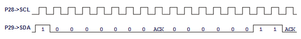
In the case of our EEPROM, that command byte tells the chip what memory address to set its pointer to. An I2C sensor might be pointed to a memory address to receive configuration values, or one that stores its sensor measurements for reading. Other devices like I/O expanders might be pointing to a memory address that contains the input or output pin states. After the command, one or more data bytes are sent to (write) or received from (read) the chip. Whether the data is one byte or many bytes depends on how the chip is designed, and it’s one of many details that get explained the device’s datasheet.
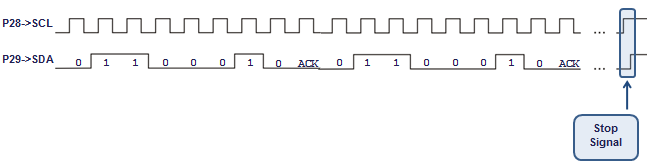
At this point, the i2c_in function has set the EEPROM’s memory address pointer. Now, it’s time to read the data bytes from the EEPROM. This is initiated by another byte with the start condition, I2C address, and read/write bit and ACK from the I2C device. This time, the read/write bit is set to 1 for a read operation, meaning the I2C device will have to start replying with data.
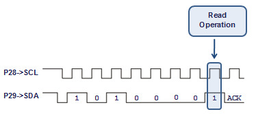
For a read operation, the Propeller continues supplying SCL pulses, but now the I2C chip controls the SDA line for 8 pulses as it replies with data, and the Propeller has to reply with an ACK or NACK on SDA during every 9th SCL pulse.