Parts
- Built-up board from First Electrical Connections with a Breadboard
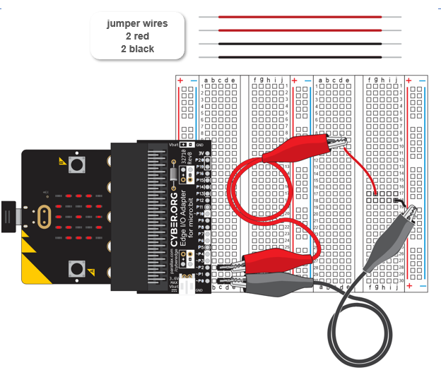
- 3” Jumper Wires - 2 red and 2 black
Circuit
- Make sure your micro:bit is still running continuity_tester.hex from First Electrical Connections with a Breadboard.
- Unplug the USB cable.
- Connect the black and red jumper wires exactly as shown here:
- Use the animation and the instructions below it to double-check your power connections.
- Optionally, download the mangnify-power-connections.mp4 clip and play and pause it between steps.
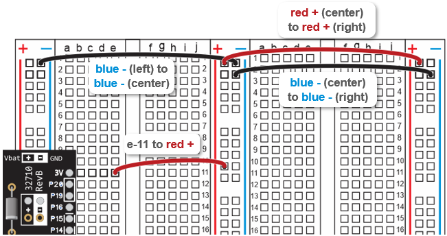
- Check your connections, and make sure they exactly match the drawing:
- Top (-) socket in left bus strip connects to top (-) socket in center bus strip, by a black wire.
- One below top (-) socket in center bus strip connects to one below top (-) socket in right bus strip, by a black wire.
- (e, 11) socket in left terminal strip connects to (+) socket in center bus strip, by a red wire.
- Top (+) socket in center bus strip connects to top (+) socket in right bus strip, by a red wire.
- Reconnect the USB cable, and verify that the LED display shows the circle-slash not connected symbol.
BLANK? Disconnect power! If the display is blank, or only displays the symbol briefly before going blank, disconnect power immediately and check your wiring for errors.