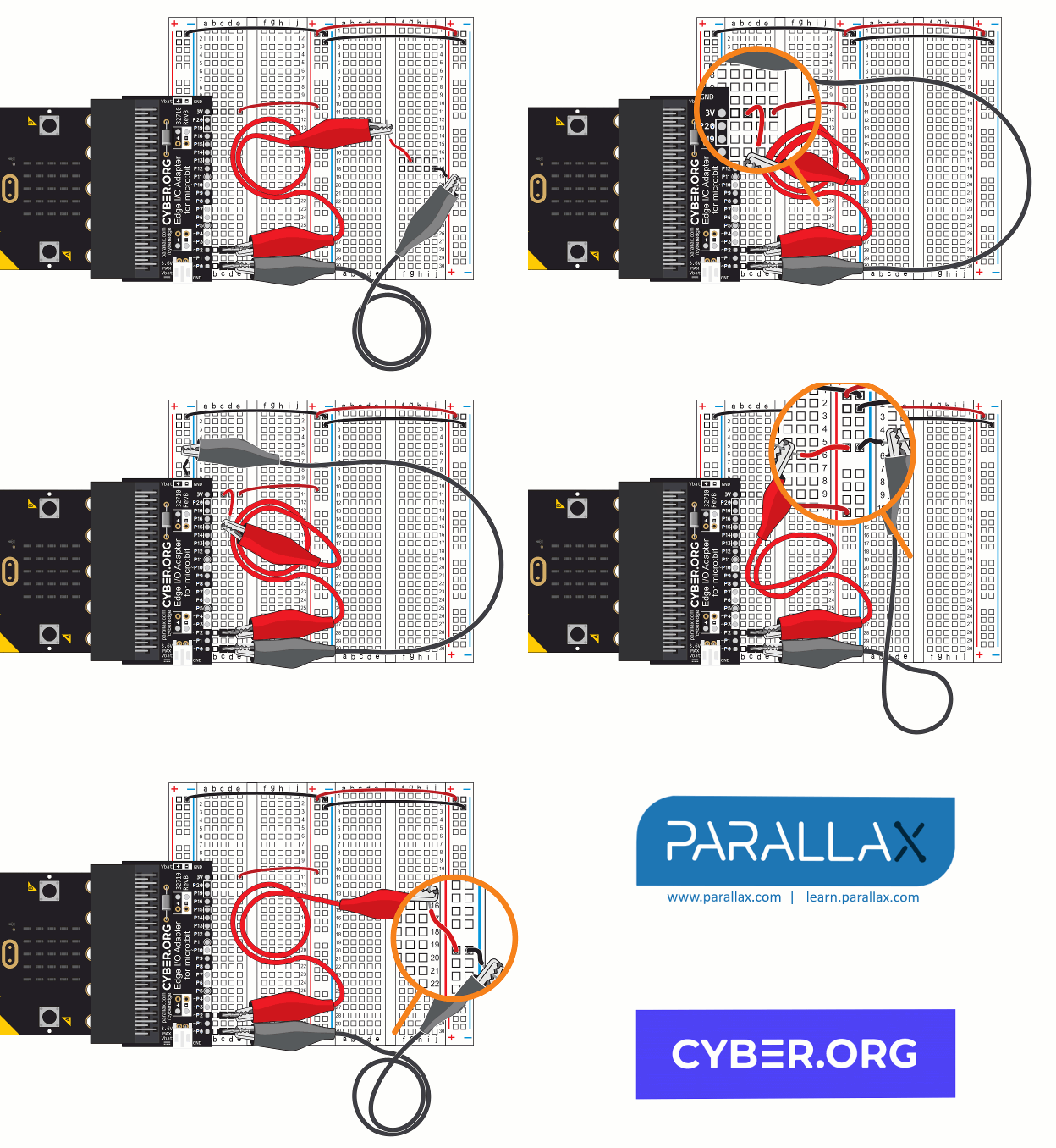
Now let’s test the supply rails, first with the Python Editor and then with CYBERscope. In these tests, you will verify that the rails now have 3.3 V.
- Use the animation and the instructions below it to connect continuity probes to your breadboard.
- Optionally, view the full-size bus-strips-verify-v-supply.mp4 clip to play and pause it between steps.
- Each step will have you plug both probes into the breadboard. After plugin them in, verify that the voltage shown in the Serial Terminal is about 3.3 V.

- Get ready to follow instructions of using the voltmeter’s positive and negative probes.
- The positive probe is the one with the red jumper wire that’s connected to the same row as P2 on the micro:bit edge adapter.
- The negative probe has the black jumper wire and is connected to the same row as P0 on the micro:bit edge adapter.
- Connect the voltmeter’s negative probe to the left bus strip’s (-) column.
- Connect the voltmeter’s positive probe to the left terminal strip’s (c, 11) socket.
- Verify that the voltage measured is very close to 3.3 V, preferably in the 3.25 to 3.35 V neighborhood. Examples:
- 3.27 V is a good measurement
- -3.27 V might mean you have your probes reversed.
- Connect the negative probe to one of the sockets in the center bus strip’s negative (-) column.
- Connect the positive probe to one of the sockets in the center bus strip’s positive (+) columns.
- Repeat this measurement to verify sockets in the center bus strip’s (+) and (-) columns.
