How It Works
An oscilloscope is typically a separate piece of equipment. If we were using one, it wouldn’t be necessary to change the code because the oscilloscope has its own processor for monitoring and displaying measurements.
This script started as button_light_blink from the Build and Test a Pushbutton activity’s Your Turn section. Since the micro:bit is functioning as its own oscilloscope, calls to plot(volts(pin0), "y0", volts(pin2), "y2") are added before and after statements that check the pushbutton and change the LED light on/off states.
Try This
In electronics, a “start pulse” from one device can cause on/off signals from another device. Those signals might contain information, like binary communication data, or they might be something like the return waves from an ultrasonic ranging pulse (that measures distance). To emulate these events, when the script you will use in this activity detects a button press, it will blink the light six times.
- Right-click button_led_blink_6x_with_plot.hex (below), and choose Save Link As...to download.
button_led_blink_6x_with_plot.hex
- Click the micro:bit Python Editor's Open button, then select and open button_led_blink_6x_with_plot.hex.
- Click Send to micro:bit.
- Click the three vertical dots ⋮ by the Send to micro:bit button, and select Disconnect.
- Start the CYBERscope:
- Go back to the CYBERscope tab.
If you already closed the CYBERscope tab, open a another tab and reopen cyberscope.parallax.com. - Click the CYBERscope's Connect button.
- In the serial port dialog, select the port with mbed in its name, and then click Connect.
- Go back to the CYBERscope tab.
Tests
- Wait until the plotted dots reach (or wraps back around to) somewhere in the 2k to 4k range.
- Press and hold the pushbutton for just a blink or two.
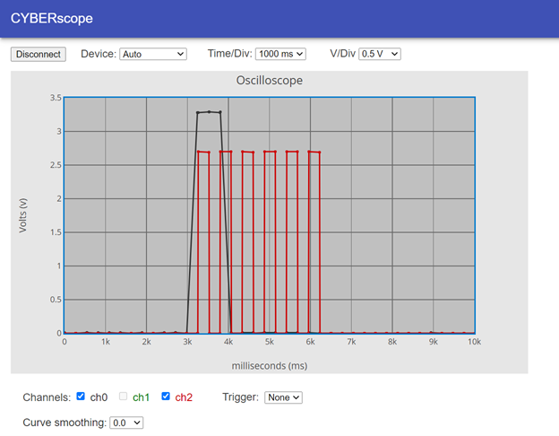
- Verify that your plot resembles the one below.
- Again, before the first pushbutton press, you might notice the red Ch2 voltage trace is plotting irregularly in the 0.5 to 1.5 V range because P13 is an input that has not been set low or high.
- See how the oscilloscope shows that the button level returned to 0 (not pressed), but the LED continues its on/off pattern for 6 repetitions?