Script: servo_plot
- Right-click servo_plot.hex (below) and select Save link as...
- Click the micro:bit Python Editor's Open button, then select and open servo_plot.hex.
- Click Send to micro:bit.
- Click the three vertical dots ⋮ by the Send to micro:bit button, and select Disconnect.
- Start the CYBERscope:
- In a different browser tab, go to cyberscope.parallax.com.
- Click the CYBERscope's Connect button.
- In the serial port dialog, select the port with mbed in its name, and then click Connect.
Tests
- Go to cyberscope.parallax.com BUT DO NOT CLICK CONNECT YET.
- Change the Device dropdown from Auto to Oscilloscope.
- Change Time/Div from 1000 ms to 5 ms.
- Change V/Div from 0.5 V to 0.75 V.
- Now, click Connect.
- Wait for at least one full plot to display. (It won’t look like the image below yet.)
- Set Trigger to Rise.
- The milliseconds (ms) trigger time control will start at 10 ms. Slide it to 5 ms.
Your display should now resemble this one:
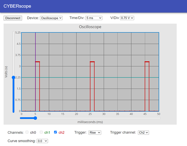
The time that the signal stays high (at 3.3 V in this case) is called the pulse width. Here, we are not going to measure the pulse width, just observe how it contains information that tells the servo what angle to hold.
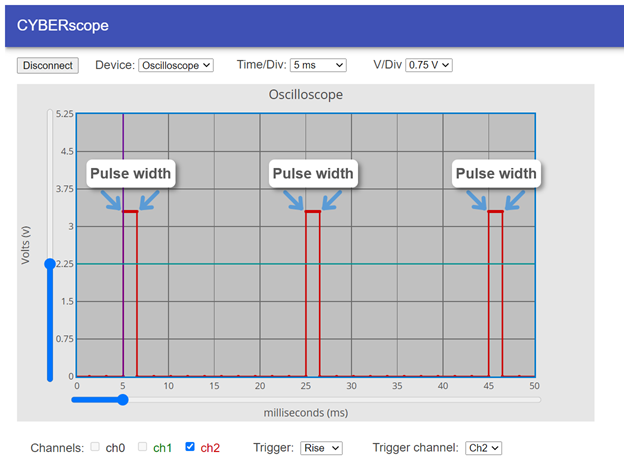
- Observe your servo and the pulse widths in your CYBERscope, and then answer these questions:
- Which servo horn angle corresponds to the narrowest pulse widths?
- Which servo horn angle corresponds to a pulse width that’s half way between the widest pulse widths?
- Which servo horn angle corresponds to the widest pulse widths?
One thing we can measure at 5 ms/div is the signal’s period (T). This was first introduced in the Connect and Blink a Light activity’s On-Off Signals page. It introduced the period of an on/off signal like a blinking light or this servo signal as tHIGH + tLOW, but take a look at what happens between the rising edges in the CYBERscope. See how the time between rising edges contains both the high (pulse width) and low times in the signal?
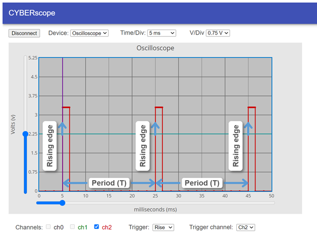
- Record the times of the rising edges in your CYBERscope, then answer these questions:
- Calculate the signal period by subtracting the millisecond time of the first rising edge from the time of the second. What is the signal period?
- If you subtract the millisecond time of the second rising edge from the third, is it the same period?
- Does the period change as the servo horn angles change?
- Review converting milliseconds to seconds in Convert Prefixes to Values, and calculate what 20 ms is in terms of seconds.
- Look up how to calculate the frequency of an on/off signal in the activity’s On-Off Signals page, and use it to calculate the frequency of this signal. Make sure to use the period in seconds, not in milliseconds in your calculations. (You figured out how many seconds in 20 milliseconds in question 7.) What is the frequency of this signal?
- How many times per second does this signal repeat itself?