How accelerometer_servo_points_up Works
This script uses math.degrees and math.atan2 from the math module. So in addition to from microbit import *, this script also imports the math module.
# accelerometer_servo_points_up

from microbit import *
import math
Using import math instead of from math import * forces any statement that uses a math module function to prepend it with the word math. Examples: math.degrees(...) and math.atan2(x, y). If you instead use from math import *, you could simply use degrees(...) or atan2(x, y). It helps make it clear that degrees and atan2 are from the math module. To save memory, you could also use from math import degrees, atan2. Instead of all the functions in the module, only degrees and atan2 would be imported, and you would call them without prepending them with math. In other words, you would be back to just calling degrees(...) and atan2(x, y).
The while True loop starts each repetition by reading the micro:bit accelerometer’s x and y-axis measurements. These measurements were introduced in Measure Accelerometer Tilt.
while True:
    x = accelerometer.get_x()
    y = accelerometer.get_y()
Next, the accelerometer measurements are converted to a rotation angle, which was introduced in Measure Rotation Angles.
angle = round( math.degrees( math.atan2(y, x) ) )
These two statements use the measured rotation angle to display the upward pointing needle. It’s the pointing-up version of the statements for pointing down that were introduced in Display Tilt Direction.
    needle = ( angle + 90 + 15 ) // 30
    display.show(Image.ALL_CLOCKS[needle])
The tests you’ve done so far involve accelerometer measurements in the 0° to 180° range. However, the range of the positions the servo needs to hold in response are in the 180° to 0° range. So, when the accelerometer reads 180°, the servo horn needs to be at 0°. When the accelerometer reads 0°, the servo horn needs to be at 180°. ...and everything in between. For example, if the accelerometer measures 150°, the servo horn needs to be pointed at 180° - 150° = 30°. Another example, if the accelerometer measures 45°, the servo horn needs to be pointed at 180° - 45° = 135°.
This if… statement executes when the accelerometer measurements are in the 0° to 180° range.   In this range, angle = 180 - angle subtracts the measured angle from 180 to produce the angle value needed to correctly position the servo.  Another way to say it is that the angle = 180 - angle statement maps the 180° to 0° input range to a 0° to 180° output range.

    if angle >= 0:
        angle = 180 - angle

The other half of a full rotation ranges from -1° to -179°.  We don’t want a servo with a 180° rotation range to try to turn any further than 180°.  So the script makes sure the servo does not respond to measurements in this range with a continue statement.  The continuestatement causes the script to repeat whatever loop it’s in, skipping any statements below it. In this script, it repeats the while True loop without reaching the value = 0.5689 * angle +25.6 and pin16.write_analog(value) statements.

    else:
        continue
The y = 0.5689x + 25.6 formula was introduced in the Connect and Test the Servo Activity’s Did You Know section to map a value in a 0° to 180° range to a value in the 26 to 128 range. Again, this makes it possible to convert the degree measurements we humans normally think about to numbers for the value variable in pin16.write_analog(value). The result is control pulses that make the servo turn to degree positions. Take a close look at value = 0.5689 * angle + 25.6. It’s the same formula with y renamed to value and x renamed to angle.
value = 0.5689 * angle + 25.6
At this point, the value variable is ready for pin16.write_analog, with numbers in the 25.6 to 128.0 range.
pin16.write_analog(value)
Try This: A Closer Look
Let’s take a closer look at how the angle = 180 - angle statement affects the value stored in the angle variable.
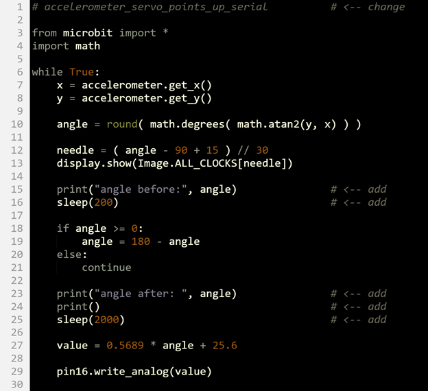
- Set the project name field to accelerometer_servo_points_up_serial.
- Change the name in the comment on line 1 to accelerometer_servo_points_up_serial.
- Add the three print and two sleep statements shown below.
- Set the Script Name field to accelerometer_servo_points_up_serial.
- Verify that your script matches the one below, then click Save.
- Click Send to micro:bit.
- Repeat the Tests section on the previous page (Script and Tests).