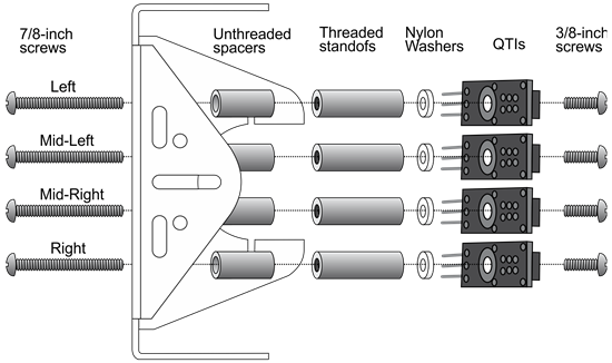
Each QTI sensor is connected to a post that is mounted on the underside of the chassis. This positions the sensors right above the ground surface.
- Assemble the QTI sensors and mount them to the underside of the ActivityBot chassis:
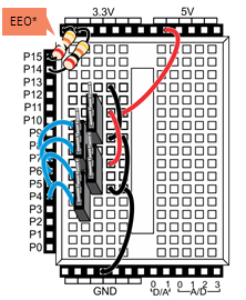
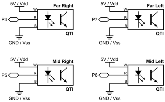
Each QTI sensor needs to connect to to 5 V power, a Propeller I/O pin, and ground. For this, you will use the four 3-pin headers from the kit to build ports on the breadboard for each sensor.
- Build the header circuits as shown in the schematic and wiring diagram below. The 3-pin headers and jumper wires are in your QTI Line Follower kit.
- Remember, DON'T use the 20 k-ohm resistors on P14 and P15 with the AB360°; they are for ActivityBot robots with External Encoders Only (EEO!).
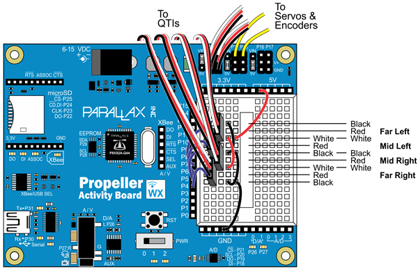
- Plug a 3-pin extension cable into each QTI sensor. Match the color of the wires to the B R W (black, red, white) labels on the sensor.
- Connect the extension cable from each QTI sensor and to its header circuit on the breadboard. Match the color of the wires to the diagram below. Take your time!
Once you have made all the connections, it is time to test them before trying line-following.