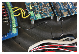
- The CENTER wire should be stripped and connected to one of the +6.5V plus side terminals on the Power Distribution Board, and the other wire (ground) should be connected to the GND terminal.
- Take one of your motor wires. Remove the connector, you will not require it.
Note: If you prefer not to have excess motor wire on your Arlo you can trim the length, or you can leave them long and just tuck the excess under the DHB-10’s PCB. How much wire to remove is up to your preference, but be careful not to cut the wires too short or they may not connect to the DHB-10 properly. Measure and double-check that your connections can still be made properly before trimming anything!
- Next, you will need to carefully remove part of the jacket covering the wires so that you can get to the ends of the wires underneath.
- Once you have exposed the wire ends, strip 1/4" from each.
- Connect the motor wires to the DHB-10 Motor Controller.
- Repeat for the second set of motor wires.
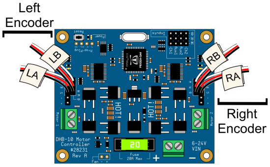
- If you labelled your encoder cables as recommended in Step 6, you can use the labels to plug your encoder cables into the DHB-10 according to the image below. If you did not label them, then connect your outside encoder cables to the headers labeled RA/LA in the image below, and the inside cables to RB/LB. Remember that your right/left is the robot's right/left when the power distribution board is on the side closest to you. Double-check your connections!
Electrical Connections, Test Code, and Troubleshooting
For making electrical connections specific to your control board, test code, and troubleshooting choose your board type from the list below:
- Propeller Activity Board WX/Original (#32912, included in Arlo Complete Robot System, or #32910)
- BASIC Stamp Board of Education (#28803)
- Board of Education Shield for Arduino (#35000, Arduino Uno also required – not included)
If using a custom board, complete the connections and then optionally move on to Section 8: Mounting the Arlo Top Deck.