Line Following with Four QTIs
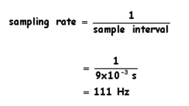
LineFollowWithCheckQtis.bs2 checks the QTIs and updates the servos every 9 ms. Remember that for a constant interval, the QTI sampling rate is the reciprocal of the sample interval. Since the sample interval is 9 ms, which is 0.009 or 9 x 10⁻³, the sampling rate is:

111 samples per second is actually more than enough for Boe-Bot line following. The servos could even go faster with higher battery voltage, and the Boe-Bot should continue following the line with ease. One thing to keep in mind is that each PBASIC command takes a fraction of a millisecond. So, to keep the sampling interval short, don't go overboard with long routines that make lots of decisions. Even more caution should be exercised when checking other sensors in addition to the QTIs each time through the main loop. If you're not careful, the sample interval can end up in the 40 ms neighborhood. The resulting sampling rate would be 25 Hz, which will probably be too low, which can lead to a variety of line tracking problems.
Reading other sensors doesn't necessarily have to delay the program that long. There are lots of techniques you can use to reduce sensor reading times, and their impact on the program's sampling rate. For example, you can use smaller capacitors for sensors other than QTIs that rely on RC decay. Also, instead of checking five additional sensors along with the QTIs between each servo pulse, your program can check one sensor along with the QTIs between each servo pulse. After five servo pulses, all five sensors will have been checked.
The next example program, LineFollowWithCheckQtis.bs2 does not check any other sensors. However, the Your Turn section following the program demonstrates how you can test various parts of a line following course to figure out how much room there is for sensor measurements in the sample interval.
Example Program – LineFollowWithCheckQtis.bs2
' LineFollowWithCheckQtis.bs2
' Navigates based on values acquired with the Check_Qtis subroutine.

' {$STAMP BS2}
' {$PBASIC 2.5}

qtis VAR Nib                         ' qti black/white states
OUTB = %1111                         ' Set OUTB bits to 1

DO                                   ' Main DO...LOOP
  GOSUB Check_Qtis                   ' Get QTI states

  SELECT qtis                        ' Control servo speeds/directions
    CASE %1000                       ' Rotate right
      PULSOUT 13, 650
      PULSOUT 12, 650
    CASE %1100                       ' Pivot right
      PULSOUT 13, 750
      PULSOUT 12, 650
    CASE %0100                       ' Curve right
      PULSOUT 13, 800
      PULSOUT 12, 650
    CASE %0110                       ' Straight ahead
      PULSOUT 13, 850
      PULSOUT 12, 650
    CASE %0010                       ' Curve left
      PULSOUT 13, 850
      PULSOUT 12, 700
    CASE %0011                       ' Pivot left
      PULSOUT 13, 850
      PULSOUT 12, 750
    CASE %0001                       ' Rotate left
      PULSOUT 13, 850
      PULSOUT 12, 850
    CASE ELSE                        ' Do nothing
      PAUSE 3
  ENDSELECT
LOOP

Check_Qtis:
' Result -> qtis variable. 0 means white surface, 1 means black surface.

  DIRB = %1111                       ' P7..P4 -> output
  PAUSE 0                            ' Delay = 230 us
  DIRB = %0000                       ' P7..P4 -> input
  PAUSE 0                            ' Delay = 230 us
  ' PULSOUT UnusedPin, 0             ' Delays = 208 + (Duration*2) us
  qtis = INB                         ' Store QTI outputs in INB
RETURN
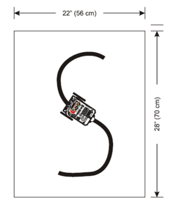
Figure 12 - Sample "S"-Shaped Boe-Bot Course

Sampling Rate Experiments
With line following competitions, it's important to test the various conditions your robot will encounter to determine how much room there is in the sample interval for other sensors. Here are just a few basic test examples. To fully prepare for a contest, you'll especially want to test the most severe obstacles the course might have.
- Make these line following obstacles:
- 45° corner
- 12-inch diameter circle
- Test LineFollowWithCheckQtis.bs2 on the obstacles. It shouldn't have any problem.
- Add PAUSE 1 to the right before the GOSUB command in the program's DO...LOOP.
- Test the program again.
- Keep increasing the PAUSE command's duration argument and re-testing the Boe-Bot on each of the obstacles.
With no PAUSE command in the DO...LOOP, the sample interval is 9 ms and the sampling rate.
- Keep increasing the PAUSE command's duration argument and note the value at which the Boe-Bot started missing the change in the line for each obstacle.
- What is the minimum sampling rate for each obstacle?
- Repeat the checklist instructions above with a 90° corner. You will have to modify the example program so that the Boe-Bot can successfully detect and navigate it before testing for the minimum sampling rate.
Self-Calibrating Code
Adapting the Calibrate_Qtis subroutine from Applied Robotics with the SumoBot (#27403) will take some work, but it's worth it. Start by reading Chapter 3, Activities #2, #3, and #4. The Calibrate_Qtis subroutine is in Activity #4. It takes RCTIME measurements on both of the SumoBot's QTIs. Then, it calculates the average of the two QTI measurements and divides that result by 4. When the QTI sees its infrared reflection, the voltage at the R pin decays very quickly. With a black surface, it takes a lot longer. By setting the threshold time at 1/4 of the average time it takes a QTI to discharge to 1.4 V over a black surface, it makes the QTIs fairly immune to fluctuations in ambient light that occur as the Boe-Bot changes direction.
Dividing the average dark QTI voltage decay time by 4 was arrived at by trial and error. With some more experimentation, you might find that you prefer to divide by 3, 5, or some other value instead.
Incorporating the Calibrate_Qtis subroutine into your program involves keeping a running total of four RCTIME measurements (one for each QTI) and dividing by 4 to take the average. After calculating the average amount of time it takes the QTIs to decay over black, divide the averaged result by 4 (a second time) to set the decay threshold time. Instead of dividing by 4 twice, you can alternately divide the sum of the dark QTI decay times by 16. The program's Check_Qtis subroutine should then use PULSOUT UnusedPin, threshold instead of PAUSE 0 between the DIRB = %1111 and DIRB = %0000 commands.
An initialization routine should also be added to a modified version of LineFollowWithCheckQtis.bs2. Whenever the program starts or is reset, its QTIs should all be over the black electrical tape until the calibration is done. The amount of time it takes to complete the calibration after a reset will vary depending on how large the program is. So, it's a good idea to add a speaker or LED circuit to signal when the calibration is complete and the Boe-Bot is done self-calibrating and ready to be placed on the course.
Other Mechanical Setups and Navigation Programs
The QTIs in this activity were mounted very close together and right below the front of the Boe-Bot. This is just one example of sensor placement and coding strategy; there are many others you can (and should) try. For example, pairs of QTIs could be placed several inches apart and several inches in front of the Boe-Bot. The code could be modified so that the Boe-Bot rolls forward so long as it does not detect a line and adjusts when it detects that the line is either under its left or right QTIs. This is just one of many different setups that might turn out to be optimum for line following performance. Especially if you are preparing for a contest, build a variety of courses and then test various programs and mechanical setups to figure out what's going to work the best. Also make sure to verify that the sampling rate can keep up with the most extreme changes in line direction that you would expect to see on the course.
