Many items you use every day have pushbuttons. Cell phones, microwave ovens, TV remotes, and computer keyboards might all have pushbuttons. Can you think of others?
Let's use a common pushbutton circuit and build a program for monitoring it with your microcontroller. Then, let's use a pushbutton's state to control LED circuits. LEDs are just one example of a device you can turn on and off with a microcontroller. Your invention might instead use pushbuttons to control circuits for motors, heating elements, or other devices.
About Pushbuttons
A pushbutton is a device that makes an electrical connection between two of its terminal leads when its button is pressed. When the button is released into its normally-open state, the electrical connection is broken and no current flows through the device. Here is the schematic symbol:
![]()
...and here is a drawing that resembles a breadboard-friendly pushbutton:
![]()
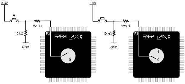
The Propeller I/O pins connected to pushbutton circuits must be set to inputs. If the pushbutton is pressed, the circuit applies 3.3 V to the I/O pin through the pushbutton, and a small amount of current also passes through the 10 kΩ resistor to ground. When the pushbutton is not pressed, the connection to the 3.3 V supply is broken, and so the circuit applies GND (0 V) to the I/O pin.
Pushbutton and LED Circuits
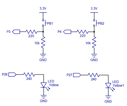
This circuit uses your board's built-in P26 and P27 LEDs, along with two pushbutton circuits you will build onto your breadboard. You may use either 220 ohm or 100 ohm resistors to connect the pushbutton circuits to the Propeller I/O pins. However, you must use 10 k-ohm resistors to connect the circuits to ground.
Parts
- (2) pushbuttons (#400-00002)
- (2) 100 ohm resistors (brown-black-brown) or (2) 220 ohm resistors (red-red-brown)
- (2) 10 k-ohm resistors (brown-black-orange)
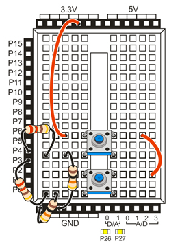
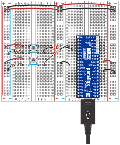
- Build the two pushbutton circuits shown in the schematic. Wiring diagrams for the Activity Board and FLiP module are given below for reference.
Test Code
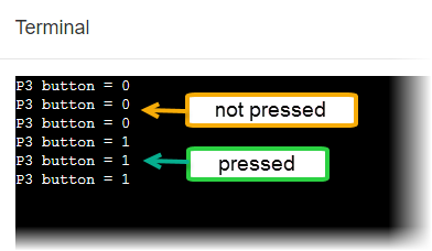
This test code will display the state of the button connected to P3 in the BlocklyProp Terminal. The Terminal displays 1 if the button is pressed, or 0 if it is not pressed.
- In BlocklyProp Solo, connect your board to your computer, and make sure the BlocklyProp Launcher is running.
- Start a new project for your board, and build the code shown below.
- Save your project, and click the Run Once button.
- When the BlocklyProp terminal opens, press and hold the P3 pushbutton. It should display a 0 when not pressed, and a 1 when pressed.
- Modify the program so that it tests the P4 pushbutton, and verify that it displays the same results in the BlocklyProp Terminal.
How it Works
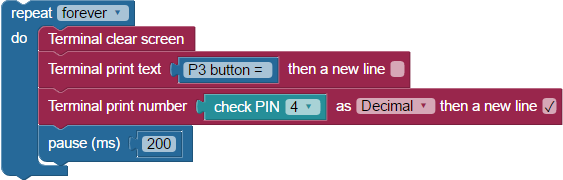
After a Terminal clear screen block, the rest of the project is in a repeat forever loop. First, a Terminal print text block supplies a useful label "P3 button = " for our data. Next comes a Terminal print number block. Inside it, the check PIN 3 block sets the P3 I/O pin to input. If the Propeller senses 0 V on P3 while the button is not pressed, the block provides a 0, and that gets printed in the Terminal. If the Propeller senses 3.3 V on P3, the block provides a 1, and that gets printed instead. A pause (ms) 200 block slows down the loop just enough to display properly before repeating.
Did You Know?
- Active-high: The pushbutton circuit you are using is called active-high because the pushbutton sends the Propeller I/O pin a 3.3 V high signal when pressed (active) or a 0 V low signal when released.
- Pull-down: The 10 k-ohm resistor in the schematic is called a pull-down resistor. It’s there so that the I/O pin will detect 3.3 V through the resistor when the button is pressed. If you leave it out, the I/O pin behaves more like an antenna, and nearby electric fields will end up controlling whether 1 or 0 is detected.
- Active-low, pull-up: Pushbuttons circuits can also be active-low. All you have to do is swap the pushbutton and 10 k-ohm resistor in the schematic. The pull-down resistor then becomes a pull-up resistor, and the I/O pin will detect 0 V when the button is pressed.
Try This
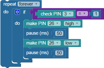
Now it is time to control an LED with a pushbutton! Remember if...do block from from the BlocklyProp Making Decisions activity? It comes in very handy for this.
- Start a new project for your board, and build the code shown below.
- Save the project, and click the Run once button.
- Verify that the P26 LED blinks if you press and hold the pushbutton connected to P3, and turns off when you release it.
Your Turn
Let's get you modify your program to make the LED connected to P27 blink when the button connected to P4 is pressed?
- Modify your Try This project to test controlling the P27 LED with the P4 pushbutton.
- Save the project, and expand the code so that the P3 button controls the P26 LED and the P4 button controls the P27 LED at the same time.