When a street light turns itself on at at dusk, or a camera knows when to use auto-flash, a light-sensing phototransistor may be at work. Let’s try using a phototransistor with the Propeller microcontroller for measuring light levels.
Introducing the Phototransistor
A transistor is like a valve that allows electric current to flow through its collector (C) and emitter (E) terminals. The base (B) terminal controls the rate of flow. Depending on the type of transistor, flow rate may be affected by voltage, by applied current, or by light as with phototransistor. The more light striking its base, the more current it will let flow.
![]()
Circuit
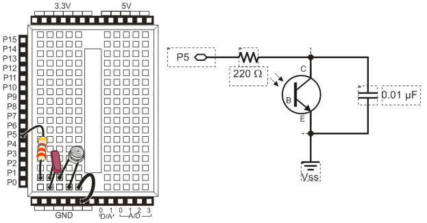
We'll use the phototransistor along with a capacitor and a resistor in a charge transfer or QT circuit. This circuit lets us read a very wide range of light levels, and it does so without needing A/D conversion. QT circuits are a simple option for a variety of analog sensors.
The QT circuit behaves very similarly to the RC time circuit used with the potentiometer. The capacitor in the circuit acts like a very small battery, and the phototransistor influences the rate its charge drains by acting as light-controlled current valve. More light = quicker capacitor discharge, less light = slower discharge. The Propeller’s job will be to measure and report the discharge time, using the RC charge/discharge block.
Parts
(1) Phototransistor (#350-00029)
(1) 0.01 µF capacitor (labeled 103, #200-01031)
(1) 0.1 µF capacitor (labeled 104, #200-01040)
(1) 220 ohm resistor (red-red-brown, #150-02210)
- Build the QT circuit shown in the schematic below. Wiring diagrams are provided for the Propeller Activity Board and Propeller FLiP module on a breadboard, for reference.
- Make sure the phototransistor leg under the case's flat spot is plugged into the bottom breadboard row, along with the jumper wire to GND.

Example Phototransistor BlocklyProp Code
The Sense Light application will display a number that corresponds with the light level the QT circuit detects.
- For best results, stay out of direct sunlight and close any window coverings. Fluorescent and indoor lighting is fine, but bright sunlight would be too much for this phototransistor to measure.
- In BlocklykProp Solo, make a new project for your board type.
- Build the project shown below, and save it.
- Click the Run with Terminal button.
- Try casting mild and deep shade over the phototransistor by cupping your hand over the board, and watch the number change in the Terminal window.
- Write down the largest and smallest numbers. The darker it gets for the phototransistor, the larger the measurement should be.
How it Works
If you tried the BlocklyProp potentiometer example, this code should look very similar! Only the I/O pin number and variable name have changed.
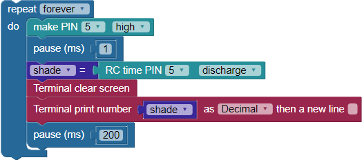
The code is inside a repeat forever loop, so it can check the circuit and update the measured value continuously. The next three blocks work together to take the capacitor discharge time measurement. They must appear in this order, with no other blocks in between.
- The block make PIN 5 high makes P5 an output and connects the QT circuit to 3.3 V.
- The pause (ms) 1 block gives the capacitor one millisecond to charge while the circuit is connected to 3.3 V. (If we were using a larger capacitor, we would have to increase that pause time.)
- The RC time PIN 5 discharge block makes P5 an input, AND starts measuring how long it takes P5 to go from sensing a 1, or a high signal above ~ 1.65 V), to sensing a 0, or a low signal below ~ 1.65 V. The block stores this measurement value, in microsecond units, in the shade variable.
After that, a Terminal clear screen block erases any old data and returns the cursor to the top-left position. Then the Terminal print number block displays the value of shade. A pause (ms) 200 block gives us enough time to see the measured value before the loop repeats.

Did You Know?
Photoresistor CdS cells are light-controlled variable resistors that also work well with RC-time measurements. CdS cells were once common, but because cadminum is environmentally unfriendly, phototransistors have replaced them in many simple applications.
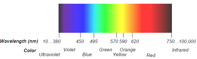
Photodiodes are also common. Though less sensitive than phototransistors, they are much faster at taking measurements, and overall better suited to the design of specialty equipment. Some devices only sense light in a certain part of the spectrum.
Infrared receivers detect light waves only in the infrared spectrum, not visible to the human eye. These sensors look for infrared light switching on/off in timed bursts, which correspond to different key presses on devices such as a TV remote.
Try This
If you use a capacitor that’s 10 times as large, your decay measurements will take ten times as long. So, the value rc_time returns will be 10 times larger.
- Find the capacitor labled 104, it’s a 0.1 µF capacitor.
- Disconnect power to your circuit, and then replace the 0.01 µF capacitor with the 0.1 µF capacitor.
- Reconnect power, and re-run the test code. You should see measurements up to 10 times larger for the same light conditions.
- Write down 3 measurements: 1) when the phototransistor is uncovered, 2) when you cast a shadown on the phototransistor with your hand, and 3) when you completely cover the phototransistor circuit with your cupped hand.
Your Turn
- Add decision-making code to your project that performs different actions as lighting conditions change across three different levels:
- When light over the potentiometer is brightest, P26 and P27 LEDs are off.
- When there is a little bit of shade cast over the potentiometer, only the P26 LED lights up.
- When it is darkest over the potentiometer, both P26 and P27 LEDs light up.