Introducing the Potentiometer and Capacitor
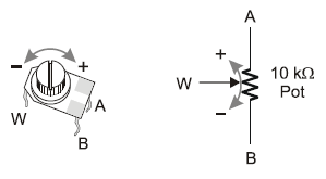
If you were to take the knob or dial off of an electronic device, you might find a potentiometer underneath it. A potentiometer is a variable resistor, and the kind shown below changes resistance as the knob turns. This particular one has a resistance range from 0 ohms to 10,000 ohms.
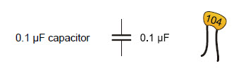
A capacitor is made of two metal plates placed very close together. When voltage is applied, electrons leave one of the plates and accumulate on the other to store an electrical charge, like a tiny battery. Its capacity to hold the charge is measured in farads. The one below is very tiny, just 0.1 microfarads. This one is not polar—it can be plugged into the circuit either way. (But be aware, some types of capacitors are polarized.)
RC Circuit
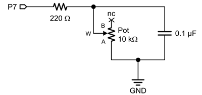
These two components together form an RC (resistor-capacitor) circuit. We can figure out the position of the potentiometer's knob by inferring the resistance it is providing to the circuit. To do this, we'll charge up the capacitor-battery, and then let the charge drain through the resistor. The higher the resistance value in ohms, the longer it will take the charge to drain. We can monitor this discharge time with a Propeller I/O pin and the RC charge/discharge block.
Parts needed
(1) 10 k-ohm potentiometer
(1) resistor 220 ohm (red-red-brown)
(1) capacitor, 0.1 µF (yellow, may be marked 104)
(1) capacitor, 0.01 µF (red, may be marked 103)
(misc.) jumper wires
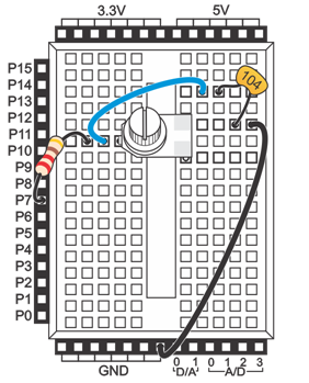
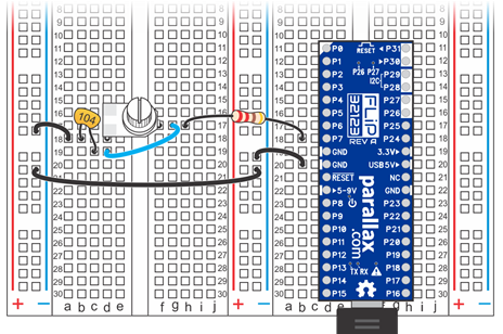
- Build the circuit shown in the schematic. Wiring diagrams for the Activity Board and Propeller FLiP module are included below for reference.
RC Discharge Time Project
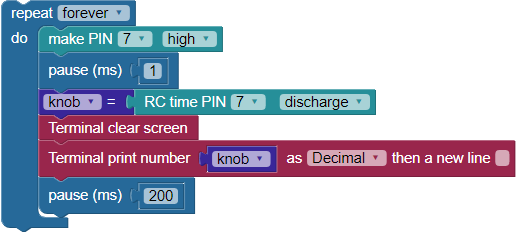
The example code below charges the capacitor, then measures the RC discharge time in microseconds and displays the value in the Terminal.
- In BlocklyProp Solo, make a new project for your board.
- Build the project shown below, and save it.
- Click the Run once button.
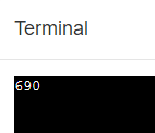
- Twist the potentiometer knob, and watch the values change in the Terminal.
- Write down the highest value.
How it Works
The code is inside a repeat forever loop, so it can check the circuit and update the measured value continuously. The next three blocks work together to take the RC discharge time measurement. They must appear in this order, with no other blocks in between.
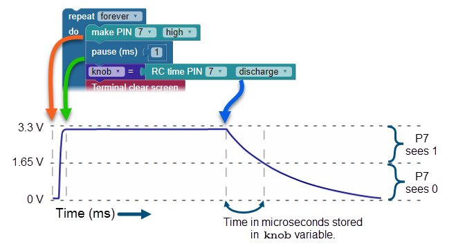
- The block make PIN 7 high sets P7 to an output and connects the RC circuit to 3.3 V.
- The pause (ms) 1 block gives the capacitor one millisecond to charge while the circuit is connected to 3.3 V. (If we were using a larger capacitor, we would have to increase that pause time.)
- The RC time PIN 7 discharge block makes P7 an input, AND starts measuring how long it takes P7 to go from sensing a 1, or a high signal above ~ 1.65 V), to sensing a 0, or a low signal below ~ 1.65 V. The block stores this measurement value, in microsecond units, in the knob variable.
After that, a Terminal clear screen block erases any old data and returns the cursor to the top-left position. Then the Terminal print number block displays the value of knob. A pause (ms) 200 block gives us enough time to see the measured value before the loop repeats.
Did You Know?
RC Time: Not Just for Pots! — The RC circuit and RC time measurement technique can be employed with other components that create a variable resistance, or otherwise influence the flow of current out of a circuit. This includes photoresistors, phototransistors, thermistors, and some types of pressure sensors, for example.
Try This
You've changed the RC discharge time across a specific range by changing the resistance in the circuit with the potentiometer's knob. Changing the size of the capacitor in the circuit will change the RC discharge time range.
- Disconnect power to your board, and replace the 0.1 µF capacitor with the 0.01 µF capacitor.
- Reconnect power, and re-run the program.
- Twist the potentiometer knob, and make note of the highest value displayed in the terminal with the new capacitor. What do you make of the results?
Your Turn
It's fun to use the potentiometer knob to control another device. Instead of displaying the value of knob, use it as a value in blocks that set the behavior of an LED, speaker, or similar device.
- Build a project where the potentiometer knob controls the blink rate of an LED.
- Build a project where the potentiometer knob controls the duration and/or frequency of a tone played on the piezospeaker.