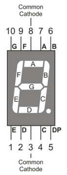
A 7-segment LED is a great way to display numbers using your Propeller microcontroller. They are made up of eight LEDs in one case. Seven bar-shaped LEDs form the segments of the digit, labelled A through G in the picture below. The eighth one is the decimal point.
You can find these in many products, such as clocks, kitchen appliances, and digital scales. This module actually uses seven LEDs arranged in a special pattern that makes it possible to show any number from 0 to 9, plus an eighth LED for a decimal point. This tutorial will show you exactly how to control the module, and use it to count.
Circuit
Each individual LED in the module needs a resistor between it and the Propeller chip’s I/O pin. When each I/O pin is set to high (outputs 3.3 V), the LED it is connected to lights up. Any resistor value between 100 Ω and 1 kΩ will work; the lower the resistance, the brighter the LED segment will shine. It’s best to use resistors of the same value so all the segments light up evenly.
Parts
(8) resistors, either 100 Ω (brown-black-brown), or 220 Ω (red-red-brown)
(1) 7-Segment Green LED (Part #350-00027)
(5) jumper wires
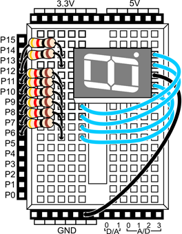
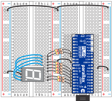
- Build the circuit shown in the schematic. Wiring diagrams for the Activity Board and Propeller FLiP module are included below for reference.

This is known as a common cathode 7-segment LED display, since the cathode for each LED segment is routed to one ground connection for the module.
Test Code
The test code will turn on all of the segments in the LED at the same time, to make sure you have built your circuit properly. It is made of just two binary set pins blocks. The first one sets all of the I/O pin directions to output, using binary value 11111111. The second one sets the ouput states to high with the same binary value, connecting each LED to 3.3 V.
- In BlocklyProp Solo, make a new project for your board.
- Build the project shown below, and save it.

- Click the Run once button.
All eight LEDs should light up - seven bar segments plus the decimal point. If they don't all light up, go back and check your circuits.
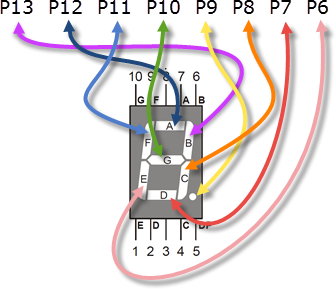
Once your circuit is working, you can try attaching different bit patterns to the set binary states block. The graphic below shows which display LED segment is connected to which Propeller I/O pin. The first, left-most bit sets the P13 LED, in order from left to right until the last, right-most bit sets the P6 LED.
- Try displaying each digit with the binary patterns in the list below:
- 0: 11100111
- 1: 10000100
- 2: 11010011
- 3: 11010110
- 4: 10110100
- 5: 01110110
- 6: 01110111
- 7: 11000100
- 8: 11110111
- 9: 11110110
Did You Know?
CC vs CA: Notice in the schematic that there is one ground connection for the module. This is known as a CC or common cathode 7-segment LED display, since the cathode for each LED segment is routed to one ground connection for the module. With a CA, or common anode display, the anode for each LED segment is connected to the same power supply pin. The cathode of each LED segment is connected to an I/O pin, and setting the I/O pin to output low (ground) will cause the segment to light up. If you were trying to use a CA 7-segment display in this tutorial, you would need to reverse all of the bits in the binary patterns,changing 1's for 0's and 0's for 1's (in addition to building your circuit as directed by its manufacturer.)
Digits and Letters Too: 7-segment LEDs can also be used to display letters. Although every letter of the English alphabet can be represented (in capital and/or lowercase form) using a single device, some letters are a bit more difficult to display in an easily recognizable way. Want to learn more? Visit the Wikipedia article about 7-segment display character representations at http://en.wikipedia.org/wiki/Seven-segment_display_character_representations.
Try This
A convenient way to display numbers on a 7-segment display is to store each binary pattern in an array and then reference the array elements later in the code. Here, we do just that, using a repeat item loop to count down the digits from 0 to 9.
Hint: each numbered element stores the binary pattern for its matching digit, 0 to 9, copied from the list above.
- Modify your project to match the one shown below, then save it.
- Run the program and watch the numbers count down.
How it Works
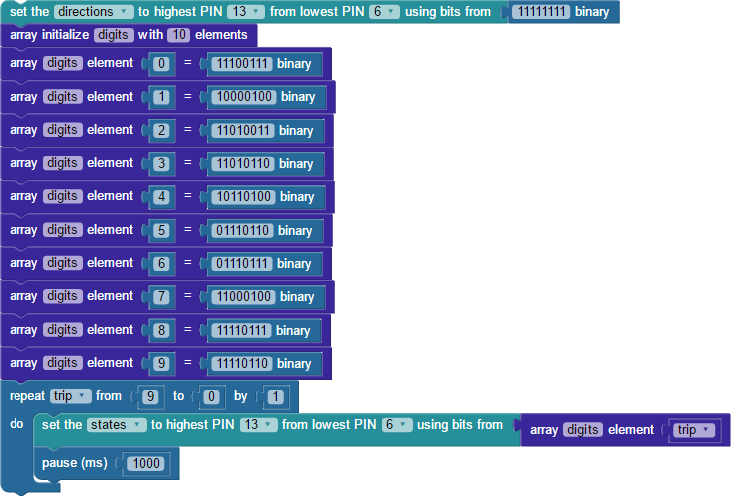
Just as in the test code, the first block sets I/O pin directions P13-P6 to output, using the binary set pins block with the binary value 11111111 attached.
Next, an array initialize block creates an array named digits that can store 10 elements (one for each digit, 0 to 9). A list of set array elment blocks fills the digits array, one element at a time. The first block defines array element 0 with the attached binary value block that holds the bit pattern for displaying a zero on the 7-segment LED. Likewise, nine more set array element blocks define the remaining digits: element 1 stores the binary pattern for displaying a 1, and so forth.
After the array is filled, the code reaches a repeat item loop, with a variable named trip to track each repetition through the loop. The block starts with trip at 9, counting down from there to 0 by 1, for a total of 10 "trips" through the loop. Inside the loop is the binary set pins block, this time with an array get element block attached. The first time through the loop, trip equals 9, so the binary set pins block uses the value stored in element 9 of the digits array. That is binary 11110110, the pattern for displaying a 9.
After a 1 second pause, the loop repeats again. This time trip equals 8, so the binary value from element 1 in the digits array is used with the binary set pins block: 11110111. The loop keeps repeating, displaying digits in descending order through its last round when trip equals 0.
Your Turn
Sometimes you may want to use array items in a different order than they are listed. One way to do that is to access the array using another array! Try modifying the program so it displays the 7-Segment LED stock code 350-00027. This will take several steps
First, you will need to add an element to the digits array, and then create and initialize a second array to hold the sequence of digits in the stock code.
- Save a copy of your project under a new name! And, save between changes to our project after each step.
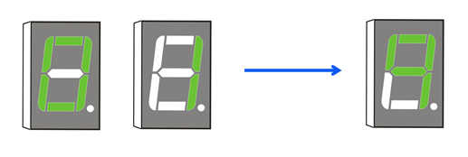
- Add an element 10 to your digits array for the dash—lighting just the center bar—using the arrows graphic above to figure out the bit pattern.
- Don't forget to update the array initialize digits block to hold an additional element!
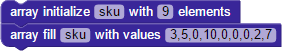
- At the top of the project, add a second array named sku, that can hold 9 elements.
- Use the array fill block to load sku with the digits in the stock code in order, using 10 for the dash.
Then, you will need to make some additions to the repeat trip... loop to make the
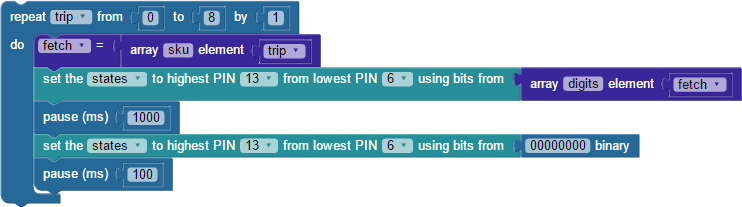
- Update the repeat trip from...loop to count upwards from 0 to 8 by 1.
- First thing inside the repeat loop, set a variable named fetch, and attach an array get element block to it that fetches the array sku element trip.
- On the binary set pins block, udpate the array get element block so it uses array digits element fetch.
- After the pause 1000 block, add another binary set pins block to turn off all of the LED segments at once.
- Last in the loop, add a 100 ms pause. Without this, you would not be able to see 0,0,0 displayed as separate digits!
- Run the project, and it should display the stock code digits in sequence.
Yes, you could have put the get array sku element trip block right inside of the get array digits block's element field, instead of using the variable fetch as a go-between. But, that is a little more confusing to understand on the first time making one array reference another, not to mention it also makes for a really long block. But, try it if you like, it is a neat trick to know for future programs!