The pictures below show the connections I made for connecting the servos and NeoPixel rings. Your connection may look a little different depending on the pins you choose to use in your project.
If you have any questions regarding the connections please email Parallax Technical Support: support@parallax.com.
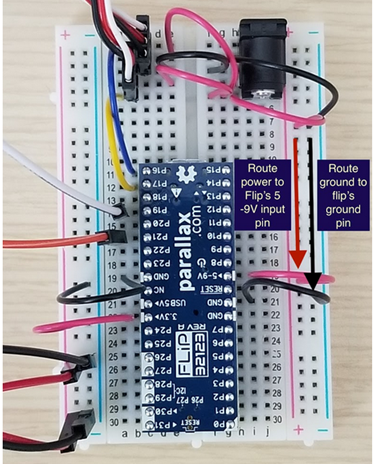
FLiP Connections (Power and Ground)
Note that the FLiP module is "upside down" to make wiring easier. The USB connection can still be used in this orientation if you do not have a barrel jack and battery pack. If using outdoors, we definitely recommend not using a USB connection for power.
If using USB power:
- GND to GND rail
- USB 5V> to PWR rail (servo/NeoPixel connections will share this rail)
If using battery pack + barrel jack:
- FLiP GND to GND rails (both sides of FLiP)
- Barrel Jack to PWR rail (rail without NeoPixel connections)
- >5-9V to PWR rail (rail without NeoPixel connections)
- 3.3V> to other PWR rail (for NeoPixel connections)
- Barrel Jack to GND rail
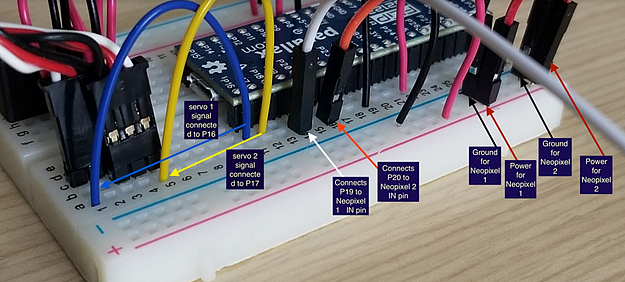
NeoPixel Connections
If using USB power, the NeoPixel rings will run off of the single USB 5V> PWR rail. If using a barrel jack/battery pack, make sure to connect them to the 3.3V> PWR rail.
NeoPixel 1:
- IN to P19
- GND to GND rail
- PWR to PWR rail
NeoPixel 2:
- IN to P20
- GND to GND rail
- PWR to PWR rail
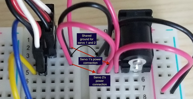
Servo Connections
If using USB power:
- Servo 1 & 2 shared GND to GND rail
- Servo 1 & 2 PWR to USB 5V> PWR rail
- Servo 1 SIG to P16
- Servo 2 SIG to P17
If using barrel jack and battery power:
- Servo 1 & 2 shared GND to GND rail
- Servo 1 & 2 PWR to >5-9V PWR rail (same as barrel jack)
- Servo 1 SIG to P16
- Servo 2 SIG to P17
- Line up your servo cables so the black wire for each is in the same breadboard row (above). This is called a shared ground connection, and you'll only need one GND wire for both servos.
- You can also wire your two servo PWR connections to the same row as the PWR from the barrel jack, as shown in the image above. The servos are able to run off of the battery pack's input voltage for this project.
Installing the Eyeball Mechanisms and Breadboard
- I used a boxcutter knife to cut a hole wide enough to install all the necessary parts into the skull.
Be careful when doing this as some decorations are made of heavier plastic or material too tough to cut through without a powered tool. Choose the safest and most efficient tool, and always wear eye protection.
- Once you cut a hole and get access to the inside of the skull, properly position the eyeballs and NeoPixel ring and then glue the eyeball mechanisms in place.
- Do the same for the breadboard and battery pack.
Before you permanently glue anything, make sure you know how best to fit all of the project parts into the skull decoration you chose. Medium-to-large skulls will be easier to work with.
Optional:
If you have access to a laser cutter you can use the file below to laser cut a platform for mounting the breadboard.