STOP: Complete each check mark in order below! Do not connect the module until you reach the appropriate step, or you may damage your Wi-Fi Module.
With the Board of Education, you can connect the WX Wi-Fi module to the AppMod Header (marked X1) or to the breadboard.
Board of Education AppMod X1 Header Instructions
- Remove all circuits from the Board of Education breadboard, AppMod header, and servo headers that are connected to even-numbered I/O pins.
- Set PWR switch to 1.
- Run this program.
' {$STAMP BS2}
' {$PBASIC 2.5}

END
- Set PWR switch to 0.
- Socket the module in the BOE AppMod header’s left column of sockets using the diagrams below as a guide.
- Verify that:
- The module’s silkscreen side (no parts) is facing left, toward the BS2;
- The module’s pins are in BOE AppMod header’s left column of sockets, closer to the even numbers;
- The AppMod header’s right column with the odd numbered labels SHOULD BE EMPTY.
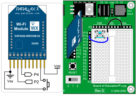
- Build the pushbutton switch on the breadboard with one terminal connected to P14 and the other connected to Vss.

Board of Education Breadboard Instructions
It is possible to build the same circuit on the Board of Education breadboard. However, this leaves much less room for other breadboard circuits, so you may need to create your own alternative parts placements in later activities.
- Remove all circuits from the breadboard.
- Connect power to your board.
- Run this program.
' {$STAMP BS2}
' {$PBASIC 2.5}

END
- Disconnect power.
- Build the Wi-Fi module and pushbutton circuits on the breadboard, as shown below.
- Verify that:
- The module’s silkscreen side (no parts) is facing left, toward the BS2
- The module’s pins are in the I/O pin sockets given in the diagram, and not in pins 12-15 (on the Board of Education it would be easy to connect something to those same I/O pins via the servo headers on accident).
