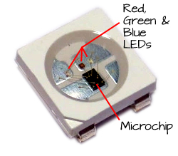
The RGB (Red, Green, Blue) LEDs used in the Running Lights are WS2812B modules. Each module contains a small microchip, a red LED, a green LED, and a blue LED:
Each module has only 4 connections: +5VDC, ground, an input, and an output. The output of one WS2812B can be connected to the input of the next WS2812B. You can chain hundreds of WS2812B modules together as long as you have enough power for the modules and a microcontroller fast enough to drive them.
The WS2812B modules look for a series of 24 bits. The first 8 bits tell the module how bright its green LED will be lit. The next 8 bits represent the brightness of the red LED, and the last 8 bits represent the brightness of the blue LED. The bits are simply pulses. When the WS2812B sees a pulse that is on for 0.35 µs and off for 0.8 µs, it interprets that as a 0 (zero), and when it sees a pulse that is on for 0.7 µs and off for 0.6 µs, it interprets that as a 1 (one).
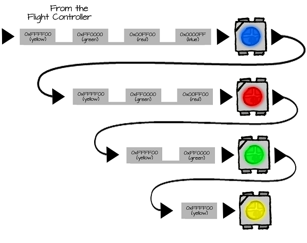
When the WS2812B receives another 24 bits, it passes them on to the next WS2812B. That module will see those 24 bits as its commands for setting its color. Any additional commands will then be passed to the next WS2812B module:
The ELEV-8 v3 Flight Controller Firmware includes a driver that generates all of the necessary pulses to drive WS2812B LED modules, since there is a WS2812B right on the board. All you have to do is edit the ELEV-8 v3 firmware to let the Flight Controller know how many LED modules are attached and what color each module should be. So, one of the firmware modifications was to tell the Flight Controller how many LED modules are attached, by editing this line in the file elev8-main.h:
#define LED COUNT 2
...to read:
#define LED COUNT 21
That let the driver support the 20 Running Light LEDs (5 on each boom) plus the first one on the Flight Controller itself:
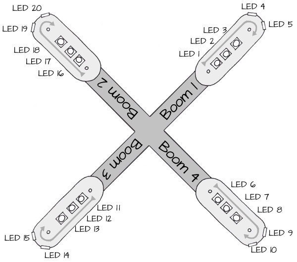
The function at the end of the elev8-main.cpp file named ALL_LED tells the driver what color to set each LED. LEDValue[] is an array that holds values for each LED. Setting the value of LEDValue[0] will set the color of the LED on the Flight controller itself. LEDValue[1] will set the color of the first LED on the Running Lights (see the diagram above).
To set an LED to a specific color, assign a 24-bit value to the LEDValue array element. For example, if you set LEDValue[1] = 0xFF0000, LED 1 will turn green:
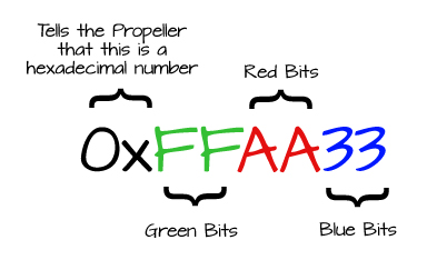
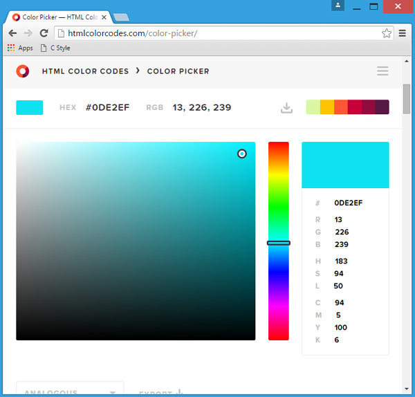
This is very similar to the way web browsers set colors. If you use an HTML color picker such as the one available at http://htmlcolorcodes.com/color-picker/ you can find the hexadecimal code for any color. To make it work for the WS2812B LED modules, you have to switch the Red and Green bits. HTML expects the bits to be in RRGGBB order, and the WS2812B expects them in GGRRBB order.
Try This
Here are some additional modes that can be added into the ALL_LED function at the end of the elev8-main.cpp file. Remember to change the line earlier in the code to state the total number of functions.
CAUTION! Remember to always re-test your ELEV-8 to make sure it is safe to fly after making any firmware modifications!
- Go back into the Flight Controller firmware and change the number highlighted in the mode below, to the number of modes you plan on adding:
    if( (Radio.Rudd < -750) && (-350 < Radio.Thro) && (Radio.Thro < 350) )
    {
      if( (Radio.Aile > 750) && (-350 < Radio.Elev) && (Radio.Elev < 350) )
      {
        RunningLightModeStep++;
        if (RunningLightModeStep >= 325)
        {
          RunningLightModeStep = 0;
          RunningLightMode++;
          if (RunningLightMode > 4)  RunningLightMode = 0;   //This must be set for the number of different modes
          for( int i=0; i <= RunningLightMode; i++ )
          {
            BeepHz(4500, 100);
            waitcnt( CNT + 5000000 );
          }
          loopTimer = CNT;
        }
      }
    }
- Copy and paste the modes below into the end of the ALL_LED function, which is at the end of elev8-main.cpp.
Stealth Mode - this turns off ALL of the LEDs including the one on the flight controller.
  if(RunningLightMode == 2)   //Stealth Mode
  {
    for( int i=0; i<led_count; i++) LEDValue[i] = 0;
  }
Motor Response Mode - when armed, the color of each boom will change from green to red as the speed of its corresponding motor changes. It is a very dim white when disarmed.
  if(RunningLightMode == 3)   //Motor Speed Visualization
  {
    int mot1 = ((Motor[OUT_FL] << 8) - (Prefs.MinThrottle << 8)) / (Prefs.MaxThrottle - Prefs.MinThrottle);
    int mot2 = ((Motor[OUT_FR] << 8) - (Prefs.MinThrottle << 8)) / (Prefs.MaxThrottle - Prefs.MinThrottle);
    int mot3 = ((Motor[OUT_BR] << 8) - (Prefs.MinThrottle << 8)) / (Prefs.MaxThrottle - Prefs.MinThrottle);
    int mot4 = ((Motor[OUT_BL] << 8) - (Prefs.MinThrottle << 8)) / (Prefs.MaxThrottle - Prefs.MinThrottle);

    LEDValue[0]  = Color;

    if( FlightEnabled )
    {
      LEDValue[1]  = LEDValue[2]  = LEDValue[3]  = LEDValue[4]  = LEDValue[5]  = ((256 - mot1) << 16) | ((mot1 - 1) << 8);
      LEDValue[6]  = LEDValue[7]  = LEDValue[8]  = LEDValue[9]  = LEDValue[10] = ((256 - mot2) << 16) | ((mot2 - 1) << 8);
      LEDValue[11] = LEDValue[12] = LEDValue[13] = LEDValue[14] = LEDValue[15] = ((256 - mot3) << 16) | ((mot3 - 1) << 8);
      LEDValue[16] = LEDValue[17] = LEDValue[18] = LEDValue[19] = LEDValue[20] = ((256 - mot4) << 16) | ((mot4 - 1) << 8);
    } else
    {
      LEDValue[1]  = LEDValue[2]  = LEDValue[3]  = LEDValue[4]  = LEDValue[5]  = 0x040404;
      LEDValue[6]  = LEDValue[7]  = LEDValue[8]  = LEDValue[9]  = LEDValue[10] = 0x040404;
      LEDValue[11] = LEDValue[12] = LEDValue[13] = LEDValue[14] = LEDValue[15] = 0x040404;
      LEDValue[16] = LEDValue[17] = LEDValue[18] = LEDValue[19] = LEDValue[20] = 0x040404;
    }
  }
Police Lights Mode - Fun, but use this mode responsibly!
  if(RunningLightMode == 4)   //Police Lights
  {
    LEDValue[0] = Color;

    if( counter & 0b01000000 )         // use a bitmask on the system counter to create a longer delay
    {
      if ( counter & 0b00100000 )      // use a bitmask on the system counter to create a medium delay
      {
        if ( counter & 0b00001000 )    // use a bitmask on the system counter to create a short delay
        {
          LEDValue[1]  = LEDValue[2]  = LEDValue[3]  = LEDValue[4]  = LEDValue[5]  = LED_Blue;
          LEDValue[6]  = LEDValue[7]  = LEDValue[8]  = LEDValue[9]  = LEDValue[10] = 0;
          LEDValue[11] = LEDValue[12] = LEDValue[13] = LEDValue[14] = LEDValue[15] = 0;
          LEDValue[16] = LEDValue[17] = LEDValue[18] = LEDValue[19] = LEDValue[20] = 0;
        } else
        {
          LEDValue[1]  = LEDValue[2]  = LEDValue[3]  = LEDValue[4]  = LEDValue[5]  = 0;
          LEDValue[6]  = LEDValue[7]  = LEDValue[8]  = LEDValue[9]  = LEDValue[10] = 0;
          LEDValue[11] = LEDValue[12] = LEDValue[13] = LEDValue[14] = LEDValue[15] = 0;
          LEDValue[16] = LEDValue[17] = LEDValue[18] = LEDValue[19] = LEDValue[20] = LED_Red;
        }
      } else
      {
        if ( counter & 0b00010000 )
        {
          LEDValue[1]  = LEDValue[2]  = LEDValue[3]  = LEDValue[4]  = LEDValue[5]  = 0;
          LEDValue[6]  = LEDValue[7]  = LEDValue[8]  = LEDValue[9]  = LEDValue[10] = LED_Blue;
          LEDValue[11] = LEDValue[12] = LEDValue[13] = LEDValue[14] = LEDValue[15] = 0;
          LEDValue[16] = LEDValue[17] = LEDValue[18] = LEDValue[19] = LEDValue[20] = 0;
        } else
        {
          LEDValue[1]  = LEDValue[2]  = LEDValue[3]  = LEDValue[4]  = LEDValue[5]  = 0;
          LEDValue[6]  = LEDValue[7]  = LEDValue[8]  = LEDValue[9]  = LEDValue[10] = 0;
          LEDValue[11] = LEDValue[12] = LEDValue[13] = LEDValue[14] = LEDValue[15] = LED_Red;
          LEDValue[16] = LEDValue[17] = LEDValue[18] = LEDValue[19] = LEDValue[20] = 0;
        }
      }
    } else
    {
      if ( counter & 0b00100000 )
      {
          LEDValue[1]  = LEDValue[2]  = LEDValue[3]  = LEDValue[4]  = LEDValue[5]  = 0;
          LEDValue[6]  = LEDValue[7]  = LEDValue[8]  = LEDValue[9]  = LEDValue[10] = LED_Blue;
          LEDValue[11] = LEDValue[12] = LEDValue[13] = LEDValue[14] = LEDValue[15] = LED_Red;
          LEDValue[16] = LEDValue[17] = LEDValue[18] = LEDValue[19] = LEDValue[20] = 0;
      } else
      {
          LEDValue[1]  = LEDValue[2]  = LEDValue[3]  = LEDValue[4]  = LEDValue[5]  = LED_Blue;
          LEDValue[6]  = LEDValue[7]  = LEDValue[8]  = LEDValue[9]  = LEDValue[10] = 0;
          LEDValue[11] = LEDValue[12] = LEDValue[13] = LEDValue[14] = LEDValue[15] = 0;
          LEDValue[16] = LEDValue[17] = LEDValue[18] = LEDValue[19] = LEDValue[20] = LED_Red;
      }
    }
  }
Your Turn
- Use what you now know to create your own LED lighting pattern!