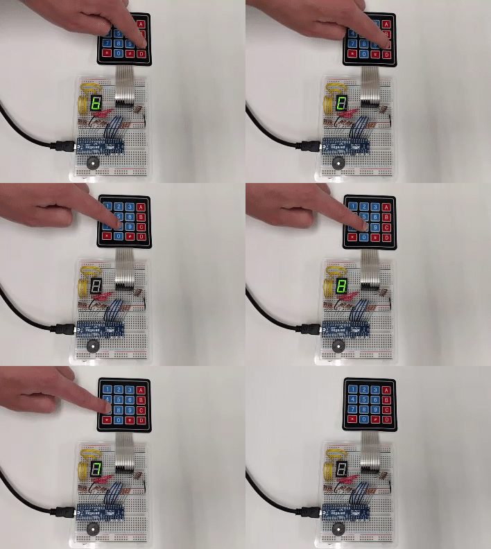
Keypads and displays provide a human interface to your applications. This project consists of a seven-segment display and 4x4 matrix keypad connected to a Propeller FLiP Module. When a keypad button is pressed the value or character will be shown on the seven-segment display and a piezo speaker will play a confirmation tone. This program provides a template which can be expanded for other purposes, including setting motor speed with the touch keypad, and positioning a servo to ten different locations.
To make this project work on an Activity Board, you will need to leave off the piezospeaker and be careful not to let resistor leads touch. Breadboard space will be limited.
Build It
This 4x4 matrix keypad circuitry is based on two other examples: Read a 4x4 Matrix Keypad (from Propeller C - Simple Devices), and the BlocklyProp Propeller Reference for 4x4 matrix keypad (Sensor > 4 x 4 Keypad). The seven-segment display circuitry is similar to the Propeller C - Simple Circuits Seven-Segment Display tutorial; however, wiring the 4x4 keypad and a seven-segment display together requires some changes to the schematic so the two systems can be viewed right-side up on your breadboard.
Parts List
- (1) - USB A to Micro B Cable (#805-00016)
- (1) - Breadboard for the FLiP Try-it Kit (#700-32023)
- (1) - Propeller FLiP Microcontroller Module (#32123)
- (1) - 4x4 Matrix Membrane Keypad (#27899)
- (1) - Piezo Speaker (#900-00001)
- (1) - 7-Segment LED (#350-00027)
- (8) - 1 kΩ Resistors (brown-black-red)
- (4) - 10 kΩ Resistors (brown-black-orange)
- (4) - 220 Ω Resistors (red-red-brown)
- Misc Jumper Wires
Pin Connections
- P0 - P7: 4x4 Matrix Membrane Keypad
- P8 - P15: 7-segment LED
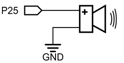
- P25: Piezo speaker
Circuit
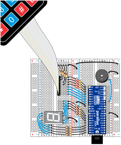
Build the circuits shown below, following the wiring diagram and schematics.
Wiring
Schematics
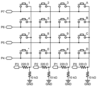
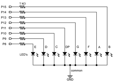
Double-check to make sure the correct resistors are used. 1 kΩ resistors for the seven-segment display, 10 kΩ resistors for the grounded pins on the 4x4 matrix keypad, and 220 Ω resistors for the P0-P3 I/O pin keypad connections.
