A 7-segment display is a great way to display numbers using your Propeller. You can find these in many products that need to display numbers in a simple way, like clocks, kitchen appliances, or digital scales. This display uses seven LEDs arranged in a special pattern that makes it possible to show any number from 0 to 9. This tutorial will show you exactly how to control the display, and use it to count.
Circuit
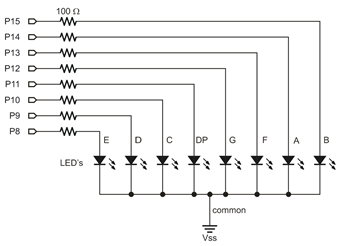
Each individual LED in the 7-segment display needs a resistor between it and the Propeller’s I/O pin. When each I/O pin is set to high (outputs 3.3 V), the LED it is connected to lights up. Any resistor value between 100 Ω and 1 kΩ will work for the LED resistor and the lower the resistance, the brighter the segment. It’s best to use resistors of the same value so all the segments light up evenly.
Parts
(8) 1 kΩ Resistors (brown-black-red). Or, you can substitute 220 Ω resistors (red-red-brown) if necessary.
(1) 7-Segment Green LED (Part #350-00027)
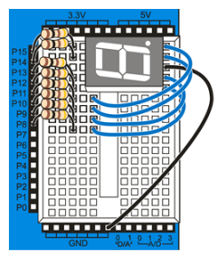
- Build the circuit for Activity Board using the diagram/schematic below (the images show 100 ohm resistors, but use 1k ohm resistors instead):
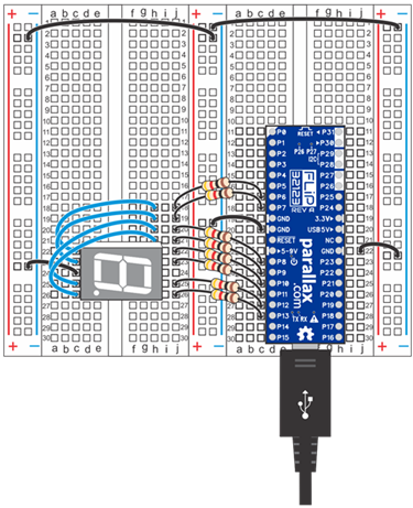
- Build the circuit for the FLiP using the diagram below:
Note: The FLiP wiring diagram uses pins 6-13, not pins 8-15. You will need to adjust your pin assignments in the code if using the FLiP.
Test Code
The test code will count from 0 to 9 on the display, with half a second between each digit.
If you haven't already installed the latest USB driver, SimpleIDE, or Learn folder, go to Propeller C - Set up SimpleIDE and Propeller C - Start Simple.
- Open the Seven Segment project from Documents\SimpleIDE\Learn\Examples\Circuits.
- Set the power switch to position 1 (if applicable for your board).
- Click the Load RAM & Run button.
- Verify that the display counts from 0 to 9.
How it Works
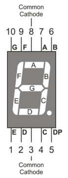
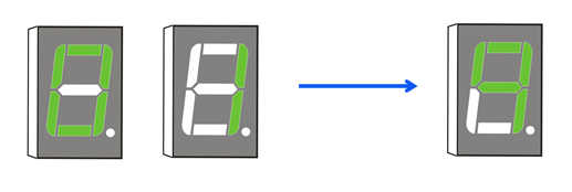
First, the code sets all the pins between 8 and 15 to outputs with set_directions(15, 8, 0b11111111). Next, the code outputs a 0 with the command set_outputs(15, 8, 0b11100111). If you look through the rest of the code, you can see that each digit has its own binary representation. The number 1, for example, is represented as 0b10000100. If you investigate more closely, you’ll notice the binary digits correspond to I/O pins, in reverse order, from 15 to 8. So the binary representation for the number 1 sets pins 15 and 10 to high. If you look at the schematic, you’ll notice that pin 15 is connected to segment B and pin 10 is connected to segment C. Referring to the diagram below, you’ll see that together, segments B and C make up the number 1.
/*
  Seven Segment.c

  Display digits on a 7-segment (common cathode) LED display.
*/

#include "simpletools.h"                      // Include simpletools

int main()                                    // main function
{
  set_directions(15, 8, 0b11111111);          // P15...P8 -> output

  set_outputs(15, 8, 0b11100111);             // 0 -> 7-segment display
  pause(500);
  set_outputs(15, 8, 0b10000100);             // 1
  pause(500);
  set_outputs(15, 8, 0b11010011);             // 2
  pause(500);
  set_outputs(15, 8, 0b11010110);             // 3
  pause(500);
  set_outputs(15, 8, 0b10110100);             // 4
  pause(500);
  set_outputs(15, 8, 0b01110110);             // 5
  pause(500);
  set_outputs(15, 8, 0b01110111);             // 6
  pause(500);
  set_outputs(15, 8, 0b11000100);             // 7
  pause(500);
  set_outputs(15, 8, 0b11110111);             // 8
  pause(500);
  set_outputs(15, 8, 0b11110110);             // 9
  pause(500);
}
Did You Know?
7-segment LEDs can also be used to display letters. You may already have seen examples of this on CD/DVD players, calculators, or microwaves. Although every letter of the English alphabet can be represented (in capital and/or lowercase form) using a single device, some letters are a bit more difficult to display in an easily recognizable way.
The capital letter “A”, for example, is easy to display using 0b11110101 as one of your outputs’ binary representations in SimpleIDE (try it!). Alternatively, letters like “w” or “k” require a bit more imagination to represent using only a single 7-segment LED; often it takes LEDs with more segments or two, side-by-side devices to accurately display them.
Want to learn more? Visit the Wikipedia article about 7-segment display character representations at http://en.wikipedia.org/wiki/Seven-segment_display_character_representations.
Try This
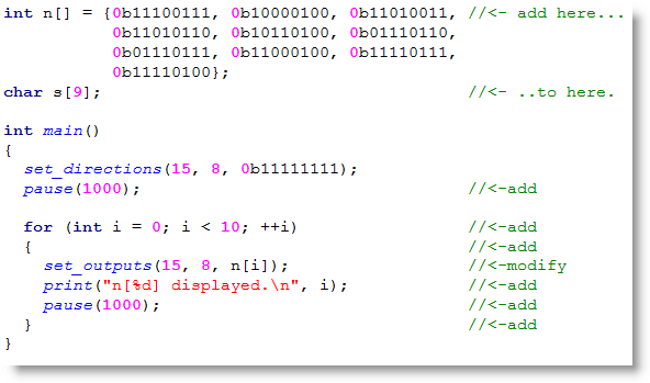
Instead of referencing each number individually, a better method to display numbers on a 7-segment display is to store each binary value in an array and then reference them later in the code. Here, we use a for loop to do just that.
- Use the Save Project As button to save a copy of your project in …Documents\SimpleIDE\My Projects.
- Modify the main function as shown below. (You can comment out most of the original set_outputs function calls.)
- Run the program and watch the numbers count up as before. Additionally, the decimal equivalent of the binary array values will be displayed in the serial terminal.
Your Turn
Since the Propeller Activity Board (original or WX version) has a built-in analog to digital converter, you can make a voltmeter using your 7-segment display. Try combining what you learned in Measure Volts with the information in this tutorial to make your display show voltages.
Note that the FLiP does not have this feature built-in, and to complete this activity you would need to add an A/D converter to your breadboard circuit.
Tip: If you have two 7-segment displays, you can use the decimal point on the first display. This involves changing the 5th bit of every value for the first display: i.e. 0b11100111 becomes 0b11101111.