Step 3 - Cutting Slots for the Wheels
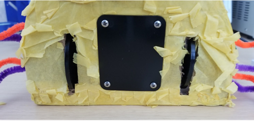
- Cut two slots onto the bottom of the piñata to let the servo wheels access the floor.
The slots are about a ¼” wide and about 2” long however, they don’t have to be exact. The most important part is to cut slots wide and long enough to let your wheels to move freely. The picture below illustrates how the wheels of the servos are supposed to look once the servos are fully installed onto the piñata. NOTE: If you didn’t laser cut custom parts it’s ok to simply glue the servo platform onto the piñata’s cardboard.
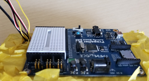
Step 4 - Cutting a Wire Hole/Mounting the Activity Board
- Cut a hole into one of the upper corners of the taco to run all the wiring through it.
- Mount the Activity Board onto the top cardboard with screws. I used two # 4-40 pan head screws and two #4-40 nuts to hold down the board.
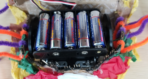
- Glue down the battery holder to the top of the two servos and run its wire harness through wire hole.
Step 5 - Install the PIR
- Install the motion sensor by placing it into the white breadboard as shown in the picture below.
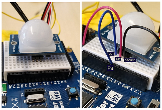
- Connect a jumper wire from the PIR’s VCC pin (middle pin) to 3.3V.
- Connect the ground pin to a GND socket located on the row of headers below the breadboard.
- Connect the OUT pin to P8.
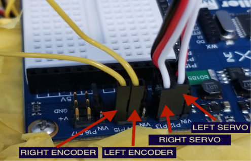
Step 6 - Connecting Servo Motors and Power
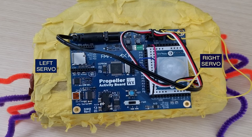
Left:
- Left Servo connects to servo header P12.
- Left Encoder wire (yellow wire) connects to servo header P14.
Right:
- Right Servo connects to servo header P13.
- Right Encoder (yellow wire) connects to servo header P15.