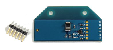
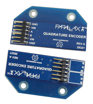
Each encoder must have a 6-pin connector soldered to its PCB. Both PCB’s are exactly the same - as are the connectors - but they are assembled in slightly different configurations.

- Insert a 6-pin right-angle male header into each of the encoder boards as shown below. Note the difference in the locations and orientations of the headers.
- Solder the headers into place.

This manner of assembly allows both sets of wires to go in the same direction from the gear head towards the back of each of the motors (as we’ll see during final assembly and mounting of the Motor Mount and Wheel assemblies).
