- Flip the main deck upright so that you can see the 12 holes in the base (between the two motor mounts).
Note that some or all of the 1/8" holes in the top of the base may not be drilled all the way through. These are “blind holes” which mean they don’t go all the way through to the other side of the base platform (yet).
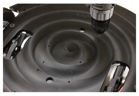
- Using a 1/8” bit, go ahead and drill all of the holes all the way through. The end result is that you’ll have a total of (12) 1/8” diameter through holes.
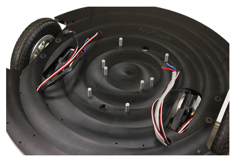
- Next, install (8) 4-40 x 5/8”screws and 5/8” long standoffs as shown below, and thread the motor and encoder wires through their respective holes. Use the (8) 5/8" standoffs and (8) 4-40 5/8" screws included in the Arlo Hardware Pack for this, and save the ones included in the base kit for mounting the battery tray later on.
NOTE: If you are mounting a Board of Education Shield + Arduino as your control board, you will need to instead use the 1.25" standoffs provided in the Arlo Hardware Pack for the (4) holes closest to the front of the Arlo (top 4 standoffs in the picture below). The BOE Shield + Arduino requires more clearance than other boards and cannot be mounted on 5/8" standoffs.