Let’s start with a sketch that makes the LED circuit connected to digital pin 13 turn on/off. First, your sketch has to tell the Arduino to set the direction of pin 13 to output, using the pinMode function: pinMode(pin, mode). The pin parameter is the number of a digital I/O pin, and mode must be either INPUT or OUTPUT.
void setup()                      // Built-in initialization block
{
  pinMode(13, OUTPUT);            // Set digital pin 13 -> output
}
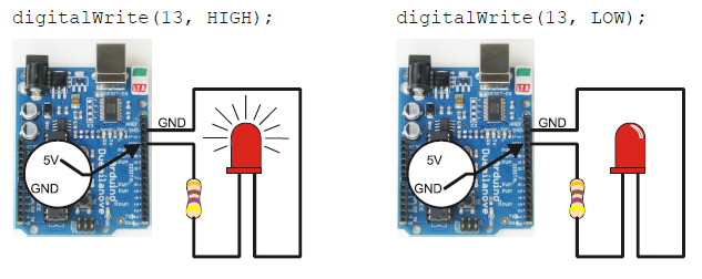
Now that digital pin 13 is set to output, we can use digitalWrite to turn the LED light on and off. Take a look at the picture below. On the left, digitalWrite(13, HIGH) makes the Arduino’s microcontroller connect digital pin 13 to 5 V, which turns on the LED. On the right, it shows how digitalWrite(13, LOW) makes it connect pin 13 to GND (0 V) to turn the LED off.
Here’s the loop function from the next sketch. First, digitalWrite(13, HIGH) turns the light on, delay(500) keeps it on for a half-second. Then digitalWrite(13, LOW) turns it off, and that’s also followed by delay(500). Since it’s inside the loop function’s block, the statements will repeat automatically. The result? The light will flash on/off once every second.
void loop()                        // Main loop auto-repeats
{
  digitalWrite(13, HIGH);          // Pin 13 = 5 V, LED emits light
  delay(500);                      // ..for 0.5 seconds
  digitalWrite(13, LOW);           // Pin 13 = 0 V, LED no light
  delay(500);                      // ..for 0.5 seconds
}
Example Sketch: HighLowLed
- Reconnect the programming cable to your board.
- Enter, save, and upload HighLowLed to your Arduino.
- Verify that the pin 13 LED turns on and off, once every second. (You may see the LED flicker a few times before it settles down into a steady blinking pattern. This happens when reprogramming the Arduino.)
/*
 Robotics with the BOE Shield - HighLowLed
 Turn LED connected to digital pin 13 on/off once every second.
 */

void setup()                                 // Built-in initialization block
{
  pinMode(13, OUTPUT);                       // Set digital pin 13 -> output
}

void loop()                                  // Main loop auto-repeats
{
  digitalWrite(13, HIGH);                    // Pin 13 = 5 V, LED emits light
  delay(500);                                // ..for 0.5 seconds
  digitalWrite(13, LOW);                     // Pin 13 = 0 V, LED no light
  delay(500);                                // ..for 0.5 seconds
}