Voltage is like a measure of electrical pressure, and measuring voltage answers questions like: “How much life is left in this battery?” and “How much does this sensor detect?”
A normal, alkaline AA battery might measure 1.6 or even 1.65 V across its terminals when it is new. After it’s been used for a while, measure it again and it may only have 1.45 V. By the time it gets down to 1.3 or 1.2 V, it is wearing out and may not be able to power whatever device it is in.
Many analog sensors output a voltage that varies in proportion to the sensor's input. Joysticks are a common example, where voltage varies depending on the position of the stick. Let’s try measuring the actual sensor inside a joystick; it’s called a potentiometer. Let’s also test the voltages on your board’s GND, 3.3 and 5 V supplies.
Circuit
This activity is not compatible with the Propeller FLiP.
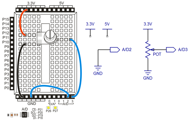
The Propeller Activity Board has four analog to digital (A/D) channels for measuring voltage. We’ll use A/D2 for probing the supply voltages. In the picture below, A/D2 is connected to GND, but we’ll also use it to probe 3.3 V and 5 V. A/D3 is connected to a potentiometer sensor’s output. As you turn the knob on top of the potentiometer, its voltage will tell you what position you have turned it to.
Parts
(1) 10 k-ohm single-turn potentiometer (#152-01031)
- Build the circuit shown here on your Propeller Activity Board (original or WX version).
If the potentiometer keeps popping out of the breadboard, use a pair of pliers to gently straighten the potentiometer's legs.
Note: This lesson is designed for the Propeller Activity Board (original or WX version). It is not compatible with the Propeller Board of Education, which uses a different A/D converter, or the Propeller FLiP, which does not have an onboard A/D converter.
Test Code
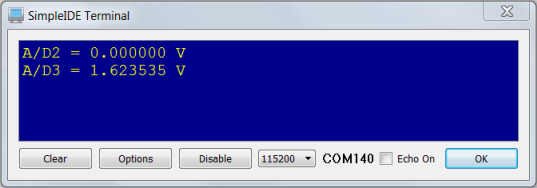
The test code will display the voltages at A/D2, which should be zero volts, and A/D3, which will vary as you turn the potentiometer’s knob. Here’s an example with the A/D2 correctly measuring GND as 0.00 V, and measuring the dial at about 1.62 V. That is about half way through the dial's range of motion, and about half of the total 0.0 to 3.3 V voltage range.
- Click SimpleIDE’s Open Project button.
- Open Measure Volts from ...Documents\SimpleIDE\Learn\Examples\Circuits.
- Click the Run with Terminal button.
- Verify that A/D2 displays as either 0 or very close to 0 V.
- TIP: Make sure to press the potentiometer onto the breadboard as you adjust the knob so that it maintains contact with the breadboard.
- Adjust the knob on your potentiometer and watch A/D3 as you do so. Does the voltage change as you turn the knob? Try twisting it from one end of its range to the other. The voltage should vary from 0 to 3.3 V.
The A/D converter compares the voltage levels it measures to GND, so that’s its 0 V. That’s why A/D2 displays 0 V, because it’s connected to GND. You can also use A/D2 your board’s 3.3 V and 5 V supplies.
- Find the wire that connects A/D2 to GND, and disconnect the end that’s plugged into the GND socket.
- Plug the end of the wire you just disconnected into the 3.3 V socket, like this:
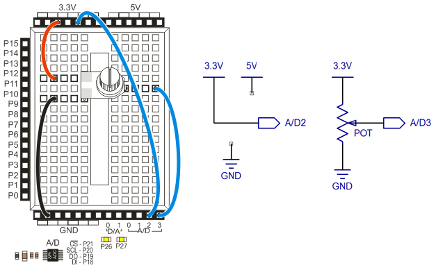
- Now, your SimpleIDE Terminal should display that A/D2 = something very close to 3.3 V.
How it Works
The code includes the adcDCpropab library, which is designed for measuring voltages using the A/D converter on the Propeller Activity Board (original or WX version). This library's function adc_init gets called first, to tell it which Propeller I/O pins are connected to the A/D converter's /CS, SCL, DO and DI pins. You will find these numbers next to the A/D converter chip, which is right below the GND sockets on your board.
After that, float v2, v3 declares two floating point variables for storing measurements. Inside the while(1) loop, v2 = adc_volts(2) stores the voltage at A/D2 into the v2 variable, and v3 = adc_volts(3) does the same for A/D3. A couple of print calls display the two voltage values, followed by a 1/10 second pause before the loop repeats.
/*
  Measure Volts.c

  Make voltmeter-style measurements with the Propeller Activity Board.
*/

#include "simpletools.h"                      // Include simpletools
#include "adcDCpropab.h"                      // Include adcDCpropab

int main()                                    // main function
{
  adc_init(21, 20, 19, 18);                   // CS=21, SCL=20, DO=19, DI=18

  float v2, v3;                               // Voltage variables

  while(1)                                    // Loop repeats indefinitely
  {
    v2 = adc_volts(2);                        // Check A/D 2
    v3 = adc_volts(3);                        // Check A/D 3

    putChar(HOME);                            // Cursor -> top-left "home"
    print("A/D2 = %f V%c\n", v2, CLREOL);     // Display volts
    print("A/D3 = %f V%c\n", v3, CLREOL);     // Display volts

    pause(100);                               // Wait 1/10 s
  }
}
Did You Know?
- AC and DC: You are measuring DC, or direct current, voltages. DC voltage is a pressure that propels current through a circuit in one direction, which is where the "direct" current name comes from. Another flavor of voltage is called AC, or alternating current. AC voltage changes, or alternates, which can cause the rate and direction of current through a circuit to change.
- A/D Converter Range: The Activity Board’s A/D converter sends numbers ranging from 0 to 4095, which represent values that range from 0 to 4.99878 V. If you supply it with 5 V, it’ll still display 4095, which is the highest it can go. These raw A/D values represent the number of 4096ths of 5 V.
Try This
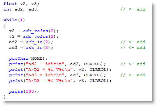
The adcDCpropab library’s adc_in function returns the actual numbers the A/D converter sends the Propeller chip. As mentioned earlier, these numbers vary from 0 to 4095, and represent voltage measurements as a number of 4096ths of 5 V.
- Use the Save Project As button to save a copy of Measure Volts in …Documents\SimpleIDE\My Projects.
- Modify your program as shown here.
- Run the program and compare the raw A/D value to the voltage displayed.
- Try using a calculator to convert ad3 to volts. The equation is:
volts = ad × 5 V ÷ 4096
Your Turn
Temperature probes are another common analog sensor with a variable-voltage output. Imagine that you have a terrarium with this kind of temperature sensor. The terrarium is too warm for its occupants if the sensor's output exceeds 1.0 V, or too cold when it goes below 0.5 V.
- Design an application that displays a status message in the Serial Terminal for three output voltage range states: too hot, just right, and too cold. It could also blink the P26 and p27 lights to indicate the three different states.