Light sensing has many uses. Think of a street light turning on at dusk, or a camera knowing when to use auto-flash. Phototransistors are a common type of light sensor used in these kinds of applications. Let’s try one with the Propeller for measuring light levels.
Circuit
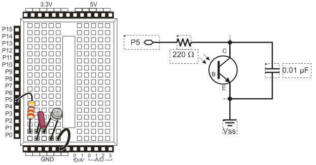
You might see a resistor and an A/D converter used with these analog light sensors elsewhere. However, the circuit here offers the ability to sense a much wider range of light levels, without needing A/D conversion. It’s called a charge transfer or QT circuit. It is a simple option for a variety of analog sensors.
Think of the 0.01 µF capacitor in the circuit as a very small battery, and the phototransistor as a light-controlled current valve. The Propeller will charge the capacitor-battery by sending an output-high signal to I/O P5. Then, the Propeller will change P5 to input and just watch what happens in the QT circuit. The phototransistor, our light controlled current valve, will control how quickly the capacitor loses its charge. More light = quicker capacitor discharge, less light = slower discharge. The Propeller’s job will be to measure the discharge time, and report that as a light measurement.
Parts
(1) Phototransistor (#350-00029)
(1) 0.01 µF capacitor (labeled 103, #200-01031)
(1) 0.1 µF capacitor (labeled 104, #200-01040)
(1) 220 ohm resistor (red-red-brown, #150-02210)
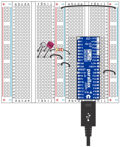
- Build the QT circuit shown below.
- Make sure the phototransistor leg under the case's flat spot is plugged into the 5-socket breadboard row that also has the jumper wire to GND.
![]()
Note: Use the schematics with any Propeller board that has a prototyping area.
Test Code
The Sense Light application will display a number that corresponds with the light level the QT circuit detects.
- For best results, stay out of direct sunlight and close the blinds. Fluorescent and indoor lighting is fine, but sunlight streaming in through the windows onto the this particular sensor would be too much for the phototransistor to measure.
- Click SimpleIDE’s Open Project button.
- Open Sense Light from ...Documents\SimpleIDE\Learn\Examples\Circuits.
- Click the Run with Terminal button.
- Try casting various levels of shade over the phototransistor, and note how the darker it gets, the larger the measurement gets.
How it Works
First, high(5) makes P5 send a 3.3 V high signal. Just as this type of signal can make an I/O pin deliver current to turn on the light, it can also deliver current to charge the capacitor. The pause(1) call gives the I/O pin time to charge the capacitor.
After that, int t = rc_time(5, 1) sets the variable t equal to the value returned by the rc_time function. This function from the simpletools library is designed to set an I/O pin to input, and then measure how long it takes for the voltage on that I/O pin to decay past the 1.65 V logic threshold.
The logic threshold is the dividing line between 1 and 0 for a Propeller input. Remember when you pressed a pushbutton and got a 1, or released it and got a 0? When the button was pressed, its I/O pin saw 3.3 V, well above 1.65 V, so the Propeller reported 1. Likewise, when the button was released, the I/O pin saw 0 V, well below 1.65 V, so the Propeller reported 0. Here, as soon as the voltage the circuit applies to the I/O pin decays to 1.65, the rc_time function stops tracking time and returns its time measurement. That time measurement gets stored in the t variable, and then displayed by print.
/*
  Sense Light.side

  Display light sensor levels.
*/

#include "simpletools.h"                      // Include simpletools

int main()                                    // main function
{
  while(1)                                    // Endless loop
  {
    high(5);                                  // Set P5 high
    pause(1);                                 // Wait for circuit to charge
    int t = rc_time(5, 1);                    // Measure decay time on P5
    print("t = %d\n", t);                     // Display decay time
    pause(100);                               // Wait 1/10th of a second
  }
}
Did You Know?
Phototransistor — The C, B, and E labels in the phototransistor schematic stand for collector, base, and emitter. These are the terminals of a transistor called a bipolar junction transistor, or BJT. The amount of current entering the base terminal controls how much current passes from C to E. Tens to hundreds of times the current entering B is what the transistor conducts from C to E. By removing the wire and placing the transistor in a clear case, the base terminal acts like a small solar collector, supplying current to the B terminal. More light means more current into B, and therefore lots more current conducted from C to E.
Capacitor — A capacitor is constructed of two metal plates that placed very close together. When voltage is applied, it charges as electrons leave one of the plates and accumulate on the other. The amount of charge a capacitor can store is measured in terms of farads (abbreviated F). Capacitors in electronic designs tend to measure in fractions of a farad. Here are some of the fraction abbreviations you might see:
- millifarads (mF) – thousandths of a farad
- microfarads (µF) – millionths of a farad
- nanofarads (nF) – billionths of a farad
- picofarads (pf) – trillionths of a farad
The 103 on the 0.01 µF capacitors case is the number of picofarads. It’s 10 + 3 zeros or 10,000, which is 1×10⁴. A trillionth, or pico is 1×10-12. Multiply the two together, and you get 1×10⁻⁸, which is also 0.01×10⁻⁶ , or 0.01 µF.
Try This
If you use a capacitor that’s 10 times as large, your decay measurements will take ten times as long. So, the value rc_time returns will be 10 times larger.
- Find the capacitor labled 104, it’s a 0.1 µF capacitor.
- Replace the 0.01 µF capacitor with the 0.1 µF capacitor.
- Re-run the test code.
- Verify that the measurement is roughly ten times larger at the same light level.
Your Turn
You have now experimented with blinking lights and light brightness, and you may also have tried speaker tones. Pick one of those and make it respond to light. Maybe with less light shining on the phototransistor, an LED will get brighter, or maybe blink faster. Or you could make a speaker tone go lower as more light shines on the phototransistor.
Hint: You may have to divide or multiply t by some value to make it useful for your output device.