Note: If you're using a Spektrum AR610 or AR8000 receiver, please follow instructions in Step 19b.
Mounting Instructions:
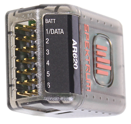
- Take your receiver and determine the correct orientation to plug the cables into the unit. Many receivers have some sort of symbol (such as, ^ + –) to indicate orientation, where ^ corresponds to the white signal wire, + corresponds to the red positive wire, and - corresponds to the black negative wire. (Spektrum SPMAR620 shown below.)
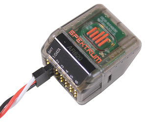
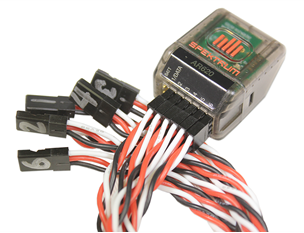
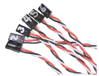
- Plug a 3-pin extension cable into the 1/Data, 2, 3, 4, 5, and 6 Channels (often abbreviated as THRO, AILE, ELEV, RUDD, GEAR, and AUX 1, respectively), keeping the orientation you determined in Instruction 1.
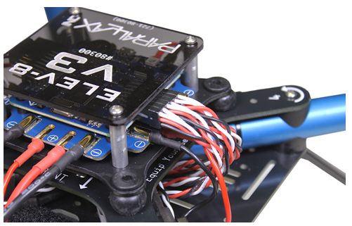
- Feed the receiver cables up through the hole in the center of the chassis as shown below.
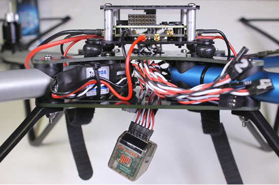
- Place the receiver on the underside of the bottom chassis plate, secure with at least one zip tie (pull tight with pliers), and cut off the “tail” of the zip tie (with diagonal cutters).
- Now, locate the pins for the receiver signal cables on the left side of the flight controller (“Receiver Port” is written on the PCB).
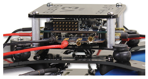
- Plug the throttle channel into the farthest left pins (labeled 1 on the flight controller PCB and also labeled 1 on the Spektrum SPMAR620) oriented vertically so that the black wire is on the bottom and white wire is on the top.
- Using the same orientation, plug in the remaining cables in the following order: THRO-AILE-ELEV-RUDD-GEAR-AUX 1.
- Move on to Step 20.