A resistor “resists” the flow of current. Voltage in a circuit with a resistor can be likened to water pressure. For a given amount of electric current, more voltage (pressure) is lost across a larger resistor than a smaller resistor that has the same amount of current passing through it. If you instead keep the resistance constant and vary the current, you can measure a larger voltage (pressure drop) across the same resistor with more current, or less voltage with less current.
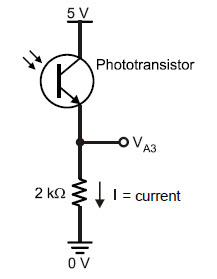
The Arduino’s analog inputs are invisible to the phototransistor circuit. So, A3 monitors the circuit but has no effect on it. Take a look at the circuit below. With 5 volts (5 V) at the top and GND (0 V) at the bottom of the circuit, 5 V of electrical pressure (voltage) makes the supply of electrons in the BOE Shield-Bot’s batteries want to flow through it.
The reason the voltage at A3 (VA3) changes with light is because the phototransistor lets more current pass when more light shines on it, or less current pass with less light. That current, which is labeled I in the circuit below, also has to pass through the resistor. When more current passes through a resistor, the voltage across it will be higher. When less current passes, the voltage will be lower. Since one end of the resistor is tied to Vss = 0 V, the voltage at the VA3 end goes up with more current and down with less current.
If you replace the 2 kΩ resistor with a 1 kΩ resistor, VA3 will see smaller values for the same currents. In fact, it will take twice as much current to get VA3 to the same voltage level, which means the light will have to be twice as bright to reach the 3.5 V level, the default voltage in HaltUnderBrightLight to make the BOE Shield-Bot stop.
So, a smaller resistor in series with the phototransistor makes the circuit less sensitive to light. If you instead replace the 2 kΩ resistor with a 10 kΩ resistor, VA3 will be 5 times larger with the same current, and it’ll only take 1/5th the light to generate 1/5th the current to get VA3 past the 3.5 V level. So, a larger resistor makes the circuit more sensitive to light.
Connected in Series When two or more elements are connected end-to-end, they are connected in series. The phototransistor and resistor in this circuit are connected in series.