The sketch HaltUnderBrightLight will make the BOE Shield-Bot go forward until the phototransistor detects light that’s bright enough to make the voltage applied to A3 exceed 3.5 V. You can change the 3.5 V value to one that’s halfway between the high and low voltage values you recorded from the last sketch.
- Calculate the half-way point between the ambient and bright light voltages you recorded from the last sketch.
- In the HaltUnderBrightLight sketch, substitute your half way point value in place of 3.5 in the statement if(volts(A3) > 3.5.
- Upload your modified version of HaltUnderBrightLight to the Arduino.
- Hold your flashlight or lamp about a foot off of the floor, and put the BOE Shield-Bot on the floor a couple feet away but pointed so it will go straight under the light.
- Move the power switch to position 2 so the BOE Shield-Bot will drive forward. How close did it get to stopping directly under the light?
- Try making adjustments to the threshold you set in the if(volts(A3) >…) statement to get the BOE Shield-Bot to park right underneath that bright light.
/*
 * Robotics with the BOE Shield - HaltUnderBrightLight
 * Display voltage of phototransistor circuit output connected to A3 in
 * the serial monitor.
 */

#include <Servo.h>                           // Include servo library

Servo servoLeft;                             // Declare left and right servos
Servo servoRight;

void setup()                                 // Built-in initialization block
{
  tone(4, 3000, 1000);                       // Play tone for 1 second
  delay(1000);                               // Delay to finish tone

  servoLeft.attach(13);                      // Attach left signal to pin 13
  servoRight.attach(12);                     // Attach right signal to pin 12

  servoLeft.writeMicroseconds(1700);         // Full speed forward
  servoRight.writeMicroseconds(1300);
}

void loop()                                  // Main loop auto-repeats
{
  if(volts(A3) > 3.5)                        // If A3 voltage greater than 3.5
  {
    servoLeft.detach();                      // Stop servo signals
    servoRight.detach();
  }
}

float volts(int adPin)                       // Measures volts at adPin
{                                            // Returns floating point voltage
 return float(analogRead(adPin)) * 5.0 / 1024.0;
}
How the Volts Function Works
The Arduino’s A0, A1…A5 sockets are connected to Atmel microcontroller pins that are configured for analog to digital conversion. It’s how microcontrollers measure voltage: they split a voltage range into many numbers, with each number representing a voltage. Each of the Arduino’s analog inputs has a 10-bit resolution, meaning that it uses 10 binary digits to describe its voltage measurement. With 10 binary digits, you can count from 0 to 1023; that’s a total of 1024 voltage levels if you include zero.
By default, the Arduino’s analogRead function is configured to use the 0…1023 values to describe where a voltage measurement falls in a 5 V scale. If you split 5 V into 1024 different levels, each level is 5/1024ths of a volt apart. 5/1024ths of a volt is approximately 0.004882813 V, or about 4.89 thousandths of a volt. So, to convert a value returned by analogRead to a voltmeter-style value, all the volts function has to do is multiply by 5 and divide by 1024.
Example:
The analogRead function returns 645; how many volts is that?
Answer:
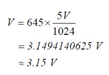
The sketches have been calling the volts function with volts(A3). When they do that, they pass A3 to its adPin parameter. Inside the function, analogRead(adPin) becomes analogRead(A3). It returns a value in the 0 to 1023 range that represents the voltage applied to A3. The analogRead call returns an integer, but since it is nested in float(analogRead(adPin), that integer value gets converted to floating point. Then, it’s multiplied by the floating point value 5.0 and divided by 1024.0, which converts it to a voltmeter value (just like we converted 645 to 3.15 V).
float volts(int adPin)                       // Measures volts at adPin
{                                            // Returns floating point voltage
 return float(analogRead(adPin)) * 5.0 / 1024.0;
}
Since return is to the left of the calculation in the volts function block, the result gets returned to the function call. The sketch PhototransistorVoltage displays the value returned by the volts function with Serial.print(volts(A3)).
HaltUnderBrightLight uses that vaule in the if(volts(A3) > 3.5) expression to bring the BOE Shield-Bot to a halt under the light.
Binary vs. Analog and Digital
A binary sensor can transmit two different states, typically to indicate the presence or absence of something. For example, a whisker sends a high signal if it is not pressed, or a low signal if it is pressed.
An analog sensor sends a continuous range of values that correspond to a continuous range of measurements. The phototransistor circuits in this activity are examples of analog sensors. They provide continuous ranges of values that correspond to continuous ranges of light levels.
A digital value is a number expressed by digits. Computers and microcontrollers store analog measurements as digital values. The process of measuring an analog sensor and storing that measurement as a digital value is called analog to digital conversion. The measurement is called a digitized measurement. Analog to digital conversion documents will also call them quantized measurements.
The Ardunio’s map Function
In the PhototransistorVoltage sketch, we converted measurements from the 0 to 1023 range to the 0.0 to 4.995 volt range for display. For other applications, you might need to convert the value to some other range of integers so that your sketch can pass it to another function, maybe for motor control, or maybe for more analysis.
That's where the Ardunio’s map function comes in handy. It's useful for “mapping” a value in one range of integers to an equivalent value in some other range. For example, let’s say you want to map a measurement in the 0 to 1024 range to a range of 1300 to 1700 for servo control. Here is an example of how you could use the map function to do it:
int adcVal = analogRead(A3);
int newAdcVal = map(adcVal, 0, 1023, 1300, 1700);
In this example, if the value of adcVal is 512 , the result of the map function for the newAdcVal call would be 1500 . So, the measurement got mapped from a point about half way through the 0..1023 range to its equivalent point in the 1300...1700 range.