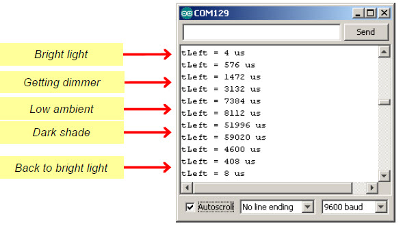
The sketch LeftLightSensor charges the capacitor in the pin 8 QT circuit, measures the voltage decay time, and displays it in the Serial Monitor. Remember, with this circuit and sketch, lower numbers mean brighter light.
We’ll be using this light-sensing technique for the rest of the chapter, so you can take the BOE Shield-Bot from one room to another without having to worry about finding the right resistors for different ambient light levels.
- If there is direct sunlight shining in through the windows, close the blinds.
- Enter and upload LeftLightSensor, and open the Serial Monitor.
- Make a note of the value displayed in the Serial Monitor.
- If the Serial Monitor does not display values or seems to get stuck after just one or two, it may mean that there’s an error in your circuit. If you see these symptoms, check your wiring and try again.
- Use your hand or a book to cast a shadow over the pin 8 phototransistor circuit.
- Check the measurement in the Serial Monitor again. The value should be larger than the first one. Make a note of it too.
- If there’s no output to the Serial Monitor, or if it is just stuck at one value regardless of light level, there could be a wiring error. Double-check your circuit (and your code too, if you hand-entered it.)
- Move the object casting the shadow closer to the top of the phototransistor to make the shadow darker. Make a note of the measurement.
- Experiment with progressively darker shadows, even cupping your hand over the phototransistor. (When it’s really dark you may have to wait a few seconds for the measurement to finish.)
/*
 * Robotics with the BOE Shield - LeftLightSensor
 * Measures and displays microsecond decay time for left light sensor.
 */

void setup()                                 // Built-in initialization block
{
  tone(4, 3000, 1000);                       // Play tone for 1 second
  delay(1000);                               // Delay to finish tone

  Serial.begin(9600);                        // Set data rate to 9600 bps
}

void loop()                                  // Main loop auto-repeats
{
  long tLeft = rcTime(8);                    // Left rcTime -> tLeft

  Serial.print("tLeft = ");                  // Display tLeft label
  Serial.print(tLeft);                       // Display tLeft value
  Serial.println(" us");                     // Display tLeft units + newline

  delay(1000);                               // 1 second delay
}
                                             // rcTime function at pin
long rcTime(int pin)                         // ..returns decay time
{
  pinMode(pin, OUTPUT);                      // Charge capacitor
  digitalWrite(pin, HIGH);                   // ..by setting pin ouput-high
  delay(1);                                  // ..for 5 ms
  pinMode(pin, INPUT);                       // Set pin to input
  digitalWrite(pin, LOW);                    // ..with no pullup
  long time  = micros();                     // Mark the time
  while(digitalRead(pin));                   // Wait for voltage < threshold
  time = micros() - time;                    // Calculate decay time
  return time;                               // Return decay time
}
Your Turn: Test the Other Phototransistor Circuit
Before moving on to navigation, you’ll need to run the same test on the right (pin 6) light sensor circuit. Both circuits have to be working well before you can move on to using them for navigation—there’s that subsystem testing again!
- In the rcTime call, change the pin parameter from 8 to 6.
- Change all instances of tLeft to tRight.
- Run the sketch, and verify that the pin 6 light sensor circuit is working.
It would also be nice to have a third sketch that tests both phototransistor circuits.
- Re-save the sketch as BothLightSensors, and update the comments.
- Replace the loop function with the one below.
- Try rotating your BOE Shield-Bot until one side is pointing toward the brightest light source in the room and the other is pointing away from it. What is the largest difference you can get between tLeft and tRight in the Serial Monitor?
void loop()                                  // Main loop auto-repeats
{
  long tLeft = rcTime(8);                    // Left rcTime -> tLeft
  Serial.print("tLeft = ");                  // Display tLeft label
  Serial.print(tLeft);                       // Display tLeft value
  Serial.print(" us      ");                 // Display tLeft units

  long tRight = rcTime(6);                   // Left rcTime -> tRight
  Serial.print("tRight = ");                 // Display tRight label
  Serial.print(tRight);                      // Display tRight value
  Serial.println(" us");                     // Display tRight units + newline

  delay(1000);                               // 1 second delay
}