Closed loop control—repeatedly measuring a value and adjusting output in proportion to error for maintaining a set point—works very well for the BOE Shield-Bot shadow vehicle. In fact, the majority of the control loop shown in the diagram below reduces to just one line of code in a sketch. This block diagram describes the proportional control process that the BOE Shield-Bot will use to control the wheel speed based on detection distance measured with the IR LED/receiver pairs.
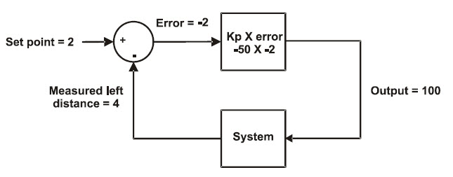
This block diagram could apply to either the left IR distance sensor and servo output or the right. In fact, your code will maintain two identical control loops, one for each side of the BOE Shield-Bot. Let’s walk through this example.
In the upper left, the set point = 2; we want the BOE Shield-Bot to maintain a zone-2 distance between itself and its leader-object. Below that, the measured distance is zone 4, so the leader-object is too far away. The arrows towards the symbols in the circle (called a summing junction) indicate that you add (+) the set point and subtract (-) the measured distance together to get the error, in this case 2 – 4 = -2.
Next, the error value feeds into the top square—an operator block. This block shows that the error gets multiplied by -50, a proportionality constant (Kp). In this example, the operator block gives us -2 × -50 = 100, so 100 is the output. In a sketch, this output value gets passed to the maneuver function. It turns the servo full speed forward to move the BOE Shield bot closer to the leader-object.
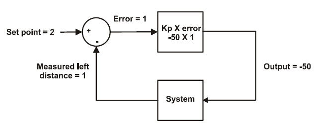
The next block diagram shows another example. This time, the measured distance is 1, meaning the leader-object is too close. So, the error is 1, and 1×–50 = -50. Passing -50 to the maneuver function turns the servo half-speed in reverse, backing the BOE Shield-Bot away from the leader-object.
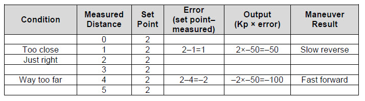
The next time through the loop, the measured distance might change, but that’s okay. Regardless of the measured distance, this control loop will calculate a value that will cause the servo to move to correct any error. The correction is always proportional to the error. The two calculations involved:
set point – measured distance = error; error x Kp = output for maneuver
…can be easily combined and re-ordered into one expression for your sketch:
Output for maneuver = (Distance set point – Measured distance) x Kp
If you want to take a look at the sketch in detail, see How FollowingShieldBot Works.
Your Turn – Verify Control Loop with Other Distances
- To prove that the proportional control loop responds correctly to all six measured distances, fill in the table below. The block diagrams have been solved for two of the six conditions, so you’ve only got four to try.