Mount the Servos on the Chassis
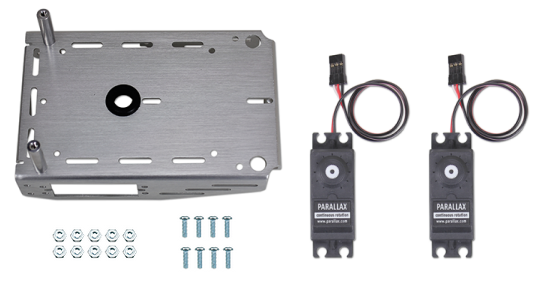
Parts List
BOE Shield-Bot Chassis, partially assembled.
(2) Parallax continuous rotation servos
(8) pan Head Screws, 3/8″ 4-40
(8) nuts, 4-40 or lock nuts
1/4" combination wrench (optional, needed for locknuts only)
masking tape
pen
Instructions:
- Decide how you want to mount your servos from the two options described and pictured below. Option 2 (right) is considered our standard small robot configuration, and our navigation code examples assume you have set up your robot this way. Code examples may need to be adjusted if you choose Option 1 (left).
Note: You can choose to use either hex nuts or locknuts to mount your servos, both are provided. Locknuts provide a tighter connection, but if your robots need frequent repair or part replacements then hex nuts are the easiest to remove and reattach quickly.
- Outside-forward (left) — the servos' mounting tabs seat outside the chassis, with their potentiometer access ports facing toward the front of the chassis. This allows easy access to adjust the potentiometers on an assembled robot, and also makes servo replacement quick. However, this gives the BOE Shield-Bot a longer, wider wheel base, so it will be a little less nimble on maneuvers and may need more pulses to make turns.
- Inside-backward (right) — the servos' mounting tabs seat inside the chassis, with their potentiometer access ports facing towards the battery pack. This positions the axles close to the center of the BOE Shield-Bot, for maximum agility. If you are diligent about centering your servos before building your BOE Shield-Bot, this causes no problems.
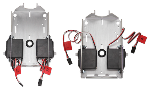
- Attach the servos to the chassis using the Phillips screws and nuts.
- Use pieces of masking tape to label the servos left (L) and right (R), as shown.