Preparing the chassis involves 3 steps:
- Removing the current development board
- Only if you want to, you can change the servo orientation now
- Upgrading to a 5-AA battery pack if necessary
Remove the Current Board
- Unplug the servos and battery plug from your robot's current development board.
- Remove the development board from the robot's standoffs. Save the #4-40 pan-head screws and whisker-post hardware!
Check the Servo Orientation
The cyber:bot robot uses the same Continuous Rotation Servos as the Boe-Bot and Shield-Bot. You do not need to change the position of the servos!
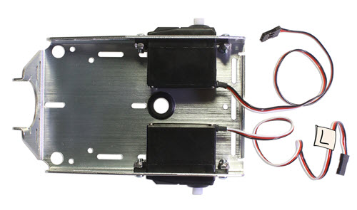
The Boe-Bot and Shield-Bot instructions install the servos with the servo mounts inside the chassis, and with the servo cables pointing back towards the tail wheel. This is perfectly fine! You can keep them this way!
However, some images in this tutorial may show the servo mounts outside of the chassis, as shown below. This makes it easier to swap out servos if needed.
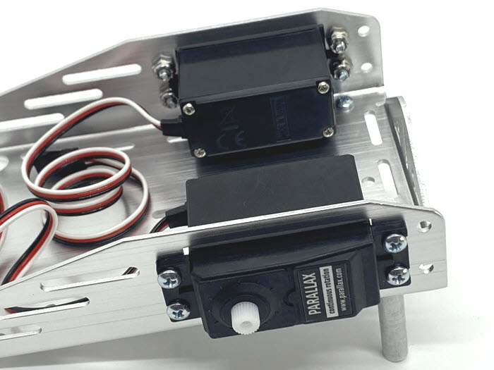
Other images may show the robot with the servo cables pointing towards the front of the robot. This makes it easy to re-center servos that have a potentiometer adjustment screw. However, this configuration' wider wheel base makes it harder for the robot to make turns. If your robot servos are ports-backward, you can still adjust the poteniometers using a long, thin screwdriver, if needed.
- If you want to re-install the servos to a different configuration, do that now.
Upgrade the Battery Pack if Needed
The cyber:bot uses a 5-AA battery pack. If your robot has a 4-AA battery pack, follow the steps below to replace it.
- Remove the 4-AA battery pack and save the Nylon flat-head screws (if you have not done so already).
- Remove the screws holding the rear standoffs to the chassis.
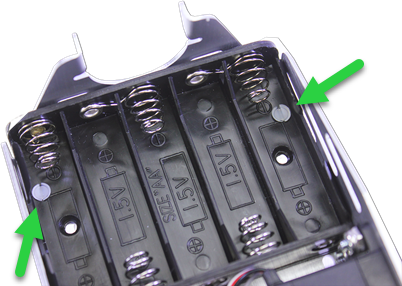
- Insert the 5-AA battery pack. It takes a bit of maneuvering: slide the edge under the the tail wheel ball, level it out, then snap it into place.
- Insert the reserved Nylon flat-head screws, threading them through the battery pack case's outermost holes.
- From the top of the chassis, thread a 1" round standoff on each screw and tighten.
- Pull the battery pack’s power cord and servo lines through the rubber grommet hole in the center of the chassis.